03.11.2022
Efficient deburring with robots
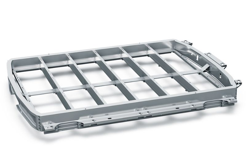
KADIA system processes battery trays
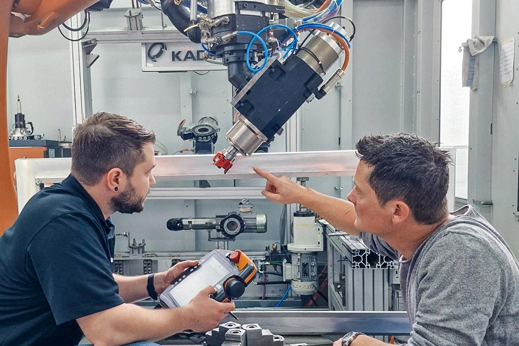
If a milling cutter is guided by a robot, the machining is fundamentally more unstable than on a machining centre. To reliably ensure the shortest cycle times in industrial production in this instance, KADIA is using MAPAL’s FlyCutter with three cutting edges in a newly developed system with three robots for deburring battery trays for electric vehicles.
The story of Nürtingen-based KADIA Produktion GmbH + Co began back in 1959 with the production of honing tools. The first honing machines were developed ten years later. The company tapped into another branch of business in 1981 with the manufacture of deburring machines. Today, KADIA is a leading specialist in honing and deburring technology and currently employs 200 people.
Its main customers are car manufacturers and suppliers, construction and agricultural machinery manufacturers, wind power plant producers and the aerospace industry. While the manufacturer offers standard machinery in different sizes for honing, in principle, custom machines are built for deburring. Customers include major machine manufacturers that bring KADIA on board as a deburring expert.
Pencil test for burrs
In mechanical machining, a distinction is made between loose and fixed burrs. After deburring, depending on what’s required, the part should have sharp edges, edge rounding or a chamfer, which is why this is also known as edge design. To assess a burr, KADIA uses a simple but meaningful test using the lead of a mechanical pencil extended by five millimetres. If it can be used to remove the burr, then the burr is loose. If the lead breaks, it’s a fixed burr, which needs to either be milled off or can be left in place, as it won’t come off later.
The size of the workpiece is also crucial to machining processes that make use of robots. Guiding the workpiece is favoured for smaller parts. The robot guides the workpiece along fixed processing units. In a tool-guided strategy, the robot arm processes a workpiece firmly clamped in place. “For bigger workpieces, I’m much more skilful with the milling cutter in hand than if I have to move the bulky part,” explains Jannik Weiss, Sales Specialist Deburring & Robotics at KADIA.
Machining in the test cell
The centrepiece of development at KADIA is a five-by-six-metre test cell with a six-axle industrial robot and a quick-release unit. This enables testing of what is set to go on to become the system. Preliminary tests determine the optimum cutting data and assess stability. The cell is home to 15 changeable units. The robot has automated access with an action radius of 2.70 m to nine of these. Each unit represents a specific function that is used for machining a part. Typically, it consists of a motor spindle with a connection and a cutting tool.
A rotary table as the seventh axle is also part of the equipment of the test cell, which also has enough space to accommodate other systems, such as coolant supply or additional process units. At KADIA, several parts are equipped for various tests in the cell at the same time.
For initial preliminary tests on a dummy part for the battery tray, KADIA used a round-insert milling cutter already in stock in. The tool proved wholly unsuitable for the task. The vibrations that occurred were so severe that even the processing spindle was damaged. Even with low cutting values, the background noise during milling was still noticeable in the adjacent building.
With the task to deliver a suitable milling cutter for the aluminium housing, MAPAL was chosen as the partner of choice. “We evaluate in advance in which tool manufacturer we see the potential for cooperation,” says Jannik Weiss. Although KADIA initially focuses on standard tools, it was a major plus for MAPAL that the tool manufacturer produces custom tools where necessary.
Two milling cutters to choose from
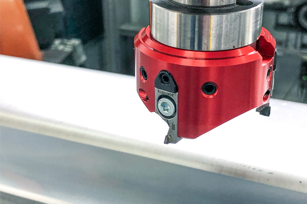
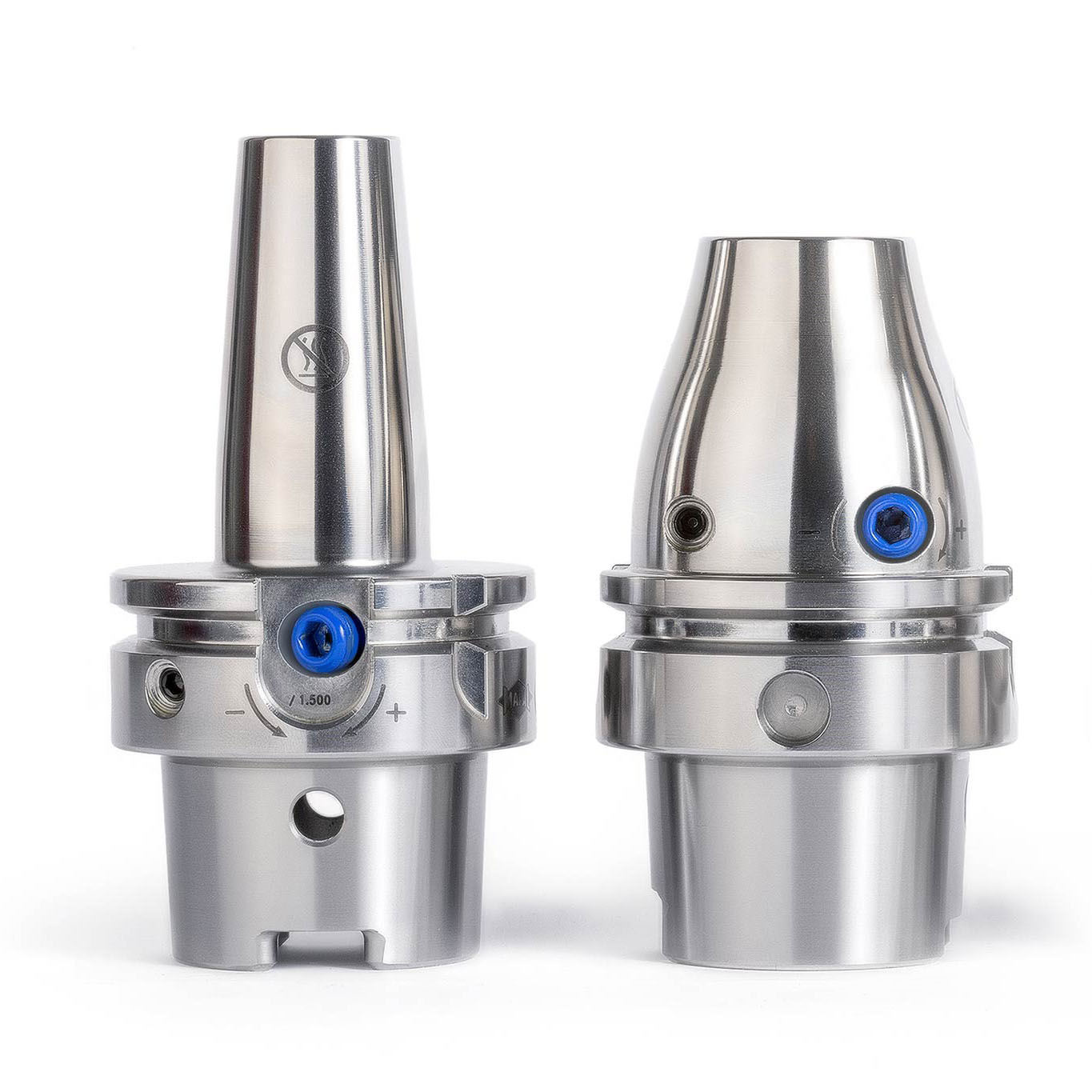
But Norbert Meier, who wanted to show the customer an alternative with the second milling cutter, had reckoned with this outcome. “We specially developed our FlyCutter for requirements like these,” he explains. MAPAL developed the lightweight tool specifically for unstable machining requirements that occur in robot applications. It is optimised for small connections such as BT30. The innovative design and use of aluminium ensure the milling head is particularly lightweight. With the diameter of 63 millimetres used at KADIA, the PCD milling head, including milling inserts, weighs just 220 grams.
The sensitive wedge adjustment make µ-precise adjustment of the milling inserts possible. The dovetail guide and an additional worm screw ensure perfect seating and high accuracy of repetition for the assembly of the milling inserts. The special, ultra-positive cutting edge geometry means only weak forces are applied to the part and the tool spindle guided by the robot.
When machining the battery tray, accuracy down to the µm is not required. In fact, to ensure the sealant applied by the automotive manufacturer holds better, a certain rawness of the surface is needed. Only the waviness must not be too high. In the tests, the milling cutter was moved beyond the limit to determine up to which point chatter marks on the relatively thin part still lay within the required tolerance.
Cutting data and positioning are key
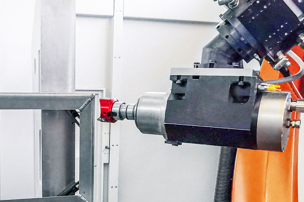
“The crux of robot processing is the interplay between tool, fixture and robot,” explains Norbert Meier. Rigidity is a fundamental issue in machining. The further the robot arm extends, the more unstable the machining. That’s why KADIA doesn’t just test various cutting data, but also various positions for the robot, in front of or beside the workpiece.
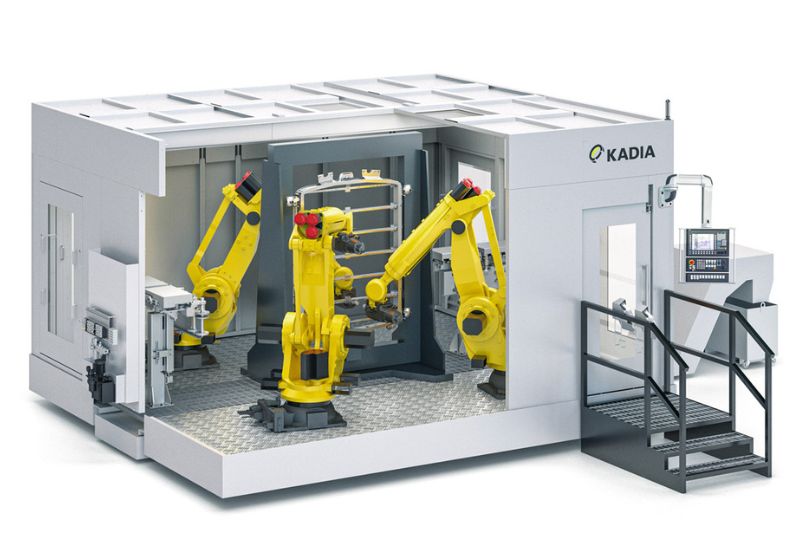
In this case, the partners determined that the optimum cutting data for a spindle speed of 11,000 rpm was a feed of 0.16 m/s and material removal rate of 0.5 mm. The FlyCutter reliably delivered very good surface quality. KADIA incorporated this test data into the concept for the custom machine. The manufacturer therefore determined that the use of three robots in one cell would be the most cost-efficient solution for series production. While two share machining on the front side, the third works on the rear. In addition to the cutting data, KADIA delivers the customer with the duration of the machining steps and the cycle time that can be achieved. Accordingly, deburring a large battery tray will take around 80 seconds. “In a robot process, such process information on cutting data is not as standard as for a CNC machine. Depending on the robot’s positioning, the same data generates different results,” says Jannik Weiss.
Due to the thoroughly positive results, KADIA and MAPAL wish to deepen their cooperation. Further testing for various machining processes is already planned.

Contact
Kathrin Rehor Public Relations Kathrin.Rehor@mapal.com Phone: +49 7361 585 3342