3D milling of CFRP prototypes from batch sizes of one
Compared to conventional metal designs, parts made of carbon fibre reinforced plastics (CFRP) are considerably lighter with the same load capacity. This offers great advantages – and not just in the aerospace industry. Low weight, high strength and low mass forces are also important in numerous other fields of application. CFRP is increasingly being used in racing cars, high-end bicycles or sports equipment, in machine engineering and for handling equipment or robots. As a development partner, MAPAL supports the development and implementation of turnkey processes with a high level of process expertise and an extensive range of tools.
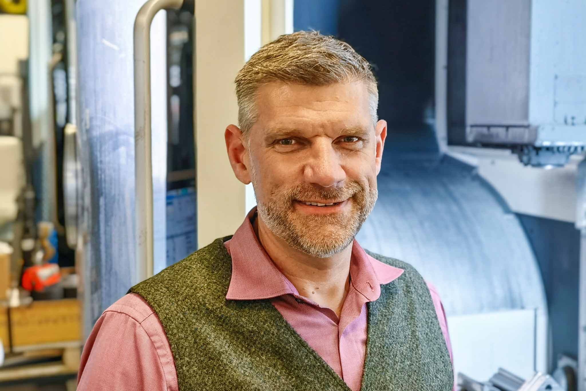
„We are a specialised industrial service provider with a wide range of technical products as well as services and solutions. The area of composites covers a wide range of semi-finished products through to complex three-dimensional component geometries made of GRP and CFRP“, explains Wulf Wagner, Product Manager of the Composite Technology business unit at ERIKS Deutschland GmbH. Particularly for products as these, customers expect support in the joint development of innovative solutions. Thanks to its exceptional engineering department, the company also designs, calculates and manufactures complete CFRP components for its customers as prototypes or in series.
CFRP moulded parts are created from „prepregs“. This semi-finished fibre product is already impregnated with a suitable resin that has not yet cured. In series production, the compression moulding process presses prepregs, which have been laid on top of each other, into mould halves with appropriately designed geometries. The hot tool cures the resin and a component with the contour of the desired part is produced. However, five-figure sums have to be invested in the metallic mould halves. This cost barrier is proving to be a drawback for many potential users who may only need one or a few parts.
Wulf Wagner, Product Manager Composite Technology at the ERIKS Deutschland GmbH.
@MAPAL
In order to offer customers a cost-effective alternative, especially in the start-up phase of a development, the standard insert material EPRATEX_CFS 100 was developed, as Wulf Wagner explains. The same prepregs are used for this. The uniformly 100 mm thick panels are available in dimensions up to 350 x 500 mm. The random orientation of the fibres in the material means that the properties are largely isotropic. The validated manufacturing process ensures reliable compliance with the properties specified in the data sheet for the structural design. Variations in dimensions, thickness and matrix system are possible on request. By machining on suitable machining centres, any desired number of pieces can be produced, from individual parts to small series.
Wanted: a turnkey machining process
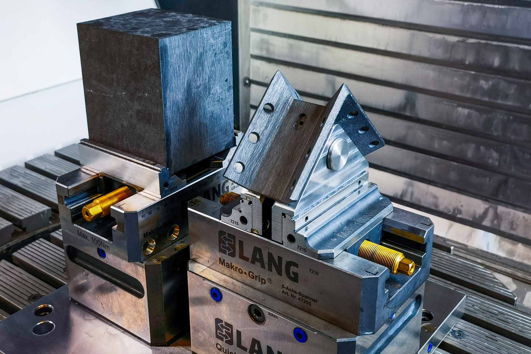
“While there are numerous suppliers of CFRP laminate panels with low wall thickness on the market, 100 mm thick panels are special”, says Sven Frank, Global Head of OEM Management at MAPAL. However, since machining CFRP is not that simple, ERIKS was looking for a turnkey validated and optimised machining process. Wulf Wagner came into contact with MAPAL. In addition to an extensive range of tools for machining CFRP workpiece materials, the precision tool manufacturer has a high level of expertise in process design and implementation. “What’s more, our research and development centre, which is eminently equipped both technically and in terms of personnel, can do test machining”, explains Frank. He emphasises: “MAPAL is happy to contribute all these resources to development projects that we conduct jointly with customers.” In doing so, the company is ready to take on any challenge. The test component chosen by ERIKS is a bracket in standard geometry from the Euro Gripper Tooling (EGT) system, which is used in large quantities in the German automotive industry in an aluminium design. The RCG Omega bracket is 30 per cent lighter and enables significant advantages in the design of Euro Gripper Tooling (EGT) systems.
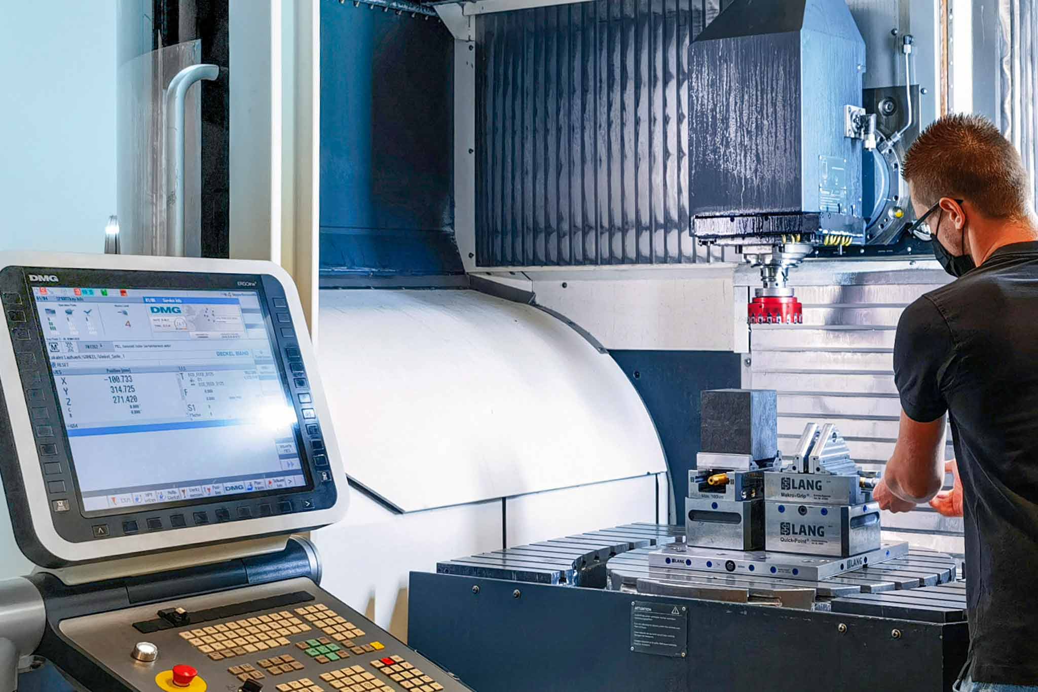
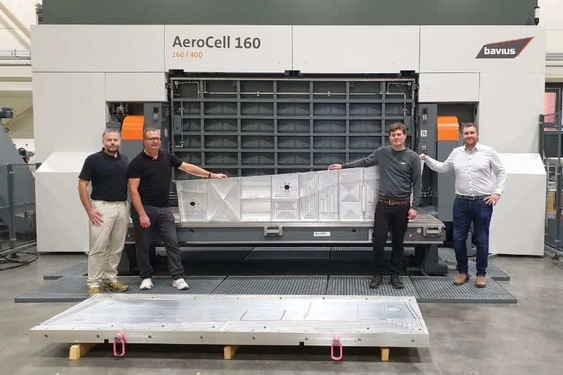
The five-axis machining was carried out on a DMU 80 monoBlock in MAPAL‘s test centre.
@MAPAL
Special demands for the tools
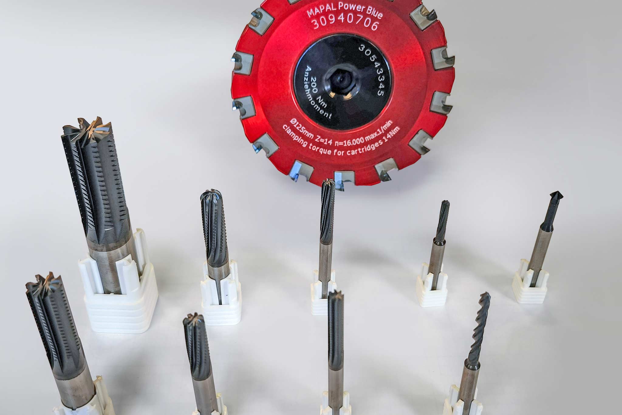
“The carbon in the carbon fibres of CFRP sometimes has diamond-like structures. Uncoated solid carbide tools cannot withstand this extremely abrasive material for long”, explains Dr Oliver Pecat, Team Leader for Aerospace Development at MAPAL. “Within one metre of milling path in a full cut, the cutting edge radius of a freshly ground solid carbide milling cutter skyrockets from 2 µm to 15 or 20 µm, while the cutting forces triple.” More cost-intensive tools with PCD (polycrystalline diamond) inserts hold up better but leave the tool designer with far fewer degrees of freedom in the geometry. For CFRP machining, MAPAL thus prefers diamond-coated solid carbide tools. MAPAL has been producing the extremely hard and abrasion-resistant CVD coating used in this case in-house since the beginning of 2021. “In total, we’ve designed the machining of the ERIKS bracket with ten tools”, says Pecat. “In addition to the EcoFeed face milling cutter with PCD milling inserts, various versions of the OptiMill-Composite-Speed solid carbide milling cutter in a roughing-finishing design and the MEGA-Drill-Composite-UDX are used, all of which are proven and process-reliable tools in the machining of composite materials.”
The test component chosen by ERIKS is machined with ten different tools from MAPAL.
@MAPAL
With MAPAL to the optimum machining process
The project allowed the R&D department to make full use of its extensive capabilities to design and validate an optimal machining process: the CAD geometry data was transferred with the aid of two of the four CAD/CAM programmes available in-house – Siemens NX and Solidcam. The developers carried out all the machining processes in comprehensive application simulations. Machine properties and clamping situations were taken into account. The development of the process steps was iterative – idea, simulation, test and evaluation. “The successful completion of the development opens up a market with a lot of future potential for both ERIKS and MAPAL”, concludes Sven Frank.
Special features of CFRP machining
“CFRP workpiece materials behave totally differently to metals during machining because the carbon fibres break brittly”, says Tizian Gühna, CAD/CAM programmer at MAPAL. With metals, the heating of the workpiece is largely based on the energy absorption through plastic deformation of the chips before breaking off. The carbon fibres in the CFRP workpiece break completely brittly as soon as the stress in the material exceeds a critical point. Hardly any heat is generated in the process. Consequently, the cutting speed can easily be increased to high values as soon as the other parameters of the process are set. Of course, the rigidity of the machine and the clamping setup as well as the avoidance of vibrations have to be taken into account.
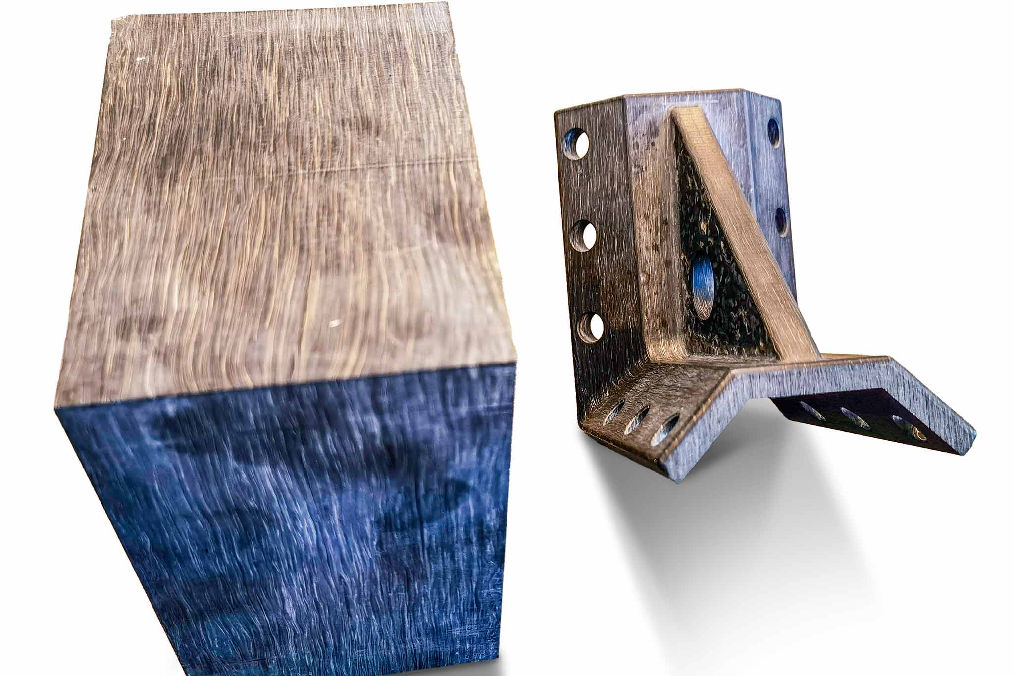
Solid, 100 mm thick CFRP block made of EPRATEX_CFS 100 and the test component produced from it by milling.
@MAPAL
Parts for numerous high-tech sectors
“In aircraft construction, there is a great demand for carbon-fibre parts that have been produced using validated processes”, says Dr Peter Müller-Hummel, Component Manager for Aerospace and Composites at MAPAL. Particularly in the interior of passenger aircraft, there are countless parts with medium to low safety classifications such as seat fasteners, cable holders and pipes. These often have to be adapted during the development and testing of a new aircraft, which results in a large demand for parts in smaller quantities. Müller-Hummel also sees a high demand for small series parts in a host of other sectors such as the automotive industry, machine engineering or medical technology, where the EPRATEX_CFS 100 panel material is ideal.
Successful cooperation, from left: Tizian Gühna, Dr Oliver Pecat (both MAPAL), Wulf Wagner (Product Manager Composite Technology at ERIKS Deutschland GmbH), Sven Frank and Dr Peter Müller-Hummel (both MAPAL).
@MAPAL
“Highly satisfied” with MAPAL as an innovation partner
“We’d been in contact with MAPAL for years and had successfully worked together to solve a wide range of tasks”, Wulf Wagner recalls. This means that there was a solid foundation of trust. This time, too, things went quickly after the initial contact: within just two weeks MAPAL had decided not just to tackle the project, but also to give it high priority. At the working level, communication with the various specialist departments and the employees there went very smoothly right from the start. The goal was achieved in the gratifyingly short time of only two and a half months. “That’s why we’ll certainly be knocking on their door again for future development projects”, Wulf Wagner sums up.