03.11.2022
ロボットによる効率的なバリ取り
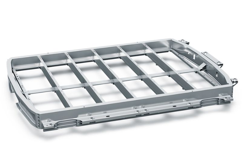
KADIAシステムがバッテリートレイを加工
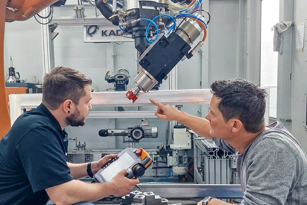
フライスカッターをロボットでガイドする場合、マシニングセンターでの加工に比べて基本的に不安定になります。KADIA 社は、このような工業生産における最短のサイクルタイムを確実に実現するため、電気自動車用バッテリートレイのバリ取り用に新たに開発した 3 台のロボットにMAPAL 社の 3 つの切れ刃を持つ フライカッターを使用しています。
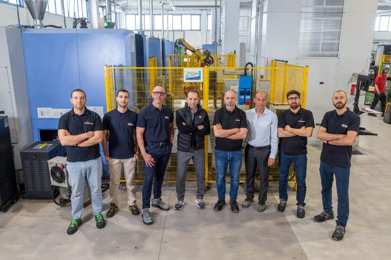
ニュルティンゲンに本社を置くKADIA Produktion GmbH + Co.社の歴史は、1959年のホーニング工具の製造から始まりました。最初のホーニング盤は創業から10年後に開発されました。1981年同社はバリ取り機の製造と共に、別の事業分野に参入しました。現在、KADIA社はホーニングおよびバリ取り技術のリーディング・スペシャリストであり、200名の従業員を擁しています。
主な顧客は、自動車メーカーやサプライヤー、建設・農業機械メーカー、風力発電所メーカー、航空宇宙産業などです。同社は、ホーニング加工用にさまざまなサイズの標準機を提供してますが、バリ取り加工用には原則としてカスタムマシンを製造しています。顧客にはバリ取りのエキスパートとしてKADIA社を採用する大手機械メーカーも含まれています。
バリの鉛筆テスト
機械加工では、緩いバリと固定されたバリを区別します。バリ取りの後、要求されるものによって、部品はシャープなエッジ、エッジの丸み、または面取りが必要で、これがエッジデザインとも呼ばれる理由です。バリを評価するために、KADIA社はシャープペンシルの芯を5ミリ出して、簡単ですが大切なテストを行います。その芯でバリを取り除くことができれば、バリは緩んでいるといえます。芯が折れるようであれば、それは固定バリであり、削り取る必要があるか、後で外れることはないのでそのままにしておくことができます。
ロボットを使用する加工プロセスでは、ワークのサイズも重要です。ワークピースをガイドすることは、小さな部品に適しています。ロボットは固定された加工ユニットに沿ってワークをガイドします。ツールガイド方式では、ロボットアームがしっかりと固定されたワークを加工します。「大きなワークピースの場合、かさばるパーツを移動させるよりもフライスカッターを手に持って加工する方がはるかに巧みです。」とKADIAのデバリング&ロボティクスのセールススペシャリスト、ヤニック・ヴァイス氏は説明します。
テストセルでの加工
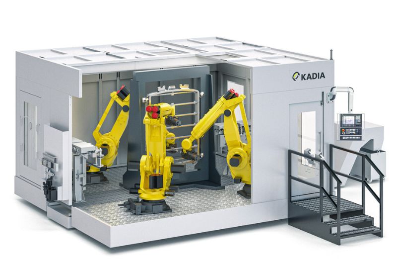
KADIA社の開発の中心は、6軸産業用ロボットとクイック・リリース・ユニットを備えた5×6メートルのテストセルです。これにより、システムになる予定のものをテストすることが可能です。予備テストでは最適な切断データを決定し、安定性を評価します。セルには15個の交換可能なユニットがあり、ロボットは、このうち9つのユニットに半径2.70mで自動アクセスすることができます。各ユニットは、部品の加工に使用される特定の機能を表しています。一般的には、接続部と切削工具を備えたモータースピンドルで構成されています。
7軸目となる回転テーブルもテストセルの設備の一部であり、クーラント供給や追加プロセスユニットなど、他のシステムを収容する十分なスペースもあります。KADIA社では、同時にセル内で様々なテストを行うために複数の部品を装備しています。
バッテリー・トレイ用のダミー部品の初期予備テストでは、KADIA社はすでに在庫していたラウンド・インサート・ミーリング・カッターを使用しました。しかしこの工具は、この作業には全く適さないことが判明しました。発生した振動は非常に激しく、加工スピンドルさえも損傷したのです。切削値が低くてもフライス加工中のバックグラウンドノイズは隣接する建物にも響いていました。
アルミニウム製ハウジングに適したフライスカッターを提供するという課題において、MAPAL社がパートナーとして選ばれました。「私たちはどの工具メーカーとの協力が可能かを事前に評価しています。」とヤニック・ヴァイス氏は言います。KADIA社は当初、標準工具に重点を置いていました。工具メーカーが必要に応じてカスタム工具を製造することは、MAPAL社にとって大きなプラスでした。
選べる2種類のフライスカッター
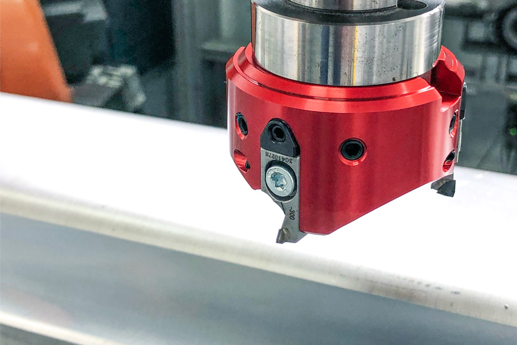
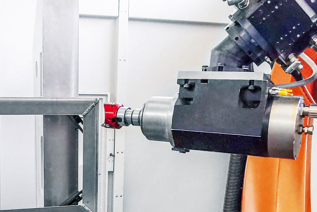
しかしノルベルト・マイヤー氏は2つ目のフライスカッターで顧客に別の選択肢を示したいと考えていました。「私たちはこのような要求のためにFly Cutterを特別に開発したのです。」と彼は説明します。MAPALはロボット用途で発生する不安定な加工要件に特化して、この軽量工具を開発しました。BT30のような小さな接続部に最適化されています。革新的な設計とアルミニウムの使用により、ミーリングヘッドは特に軽量です。KADIAで使用されている直径63ミリのPCDミリングヘッドは、ミリングインサートを含めてわずか220グラムです。
繊細なウェッジ調整により、ミーリングチップのμ精度の調整が可能です。アリ溝ガイドと追加ウォームスクリューにより、ミーリングチップの完璧な着座と高精度の繰返し精度が保証されます。特殊な超ポジティブ刃先形状により、ワークとロボットにガイドされたツールスピンドルには弱い力しかかかりません。
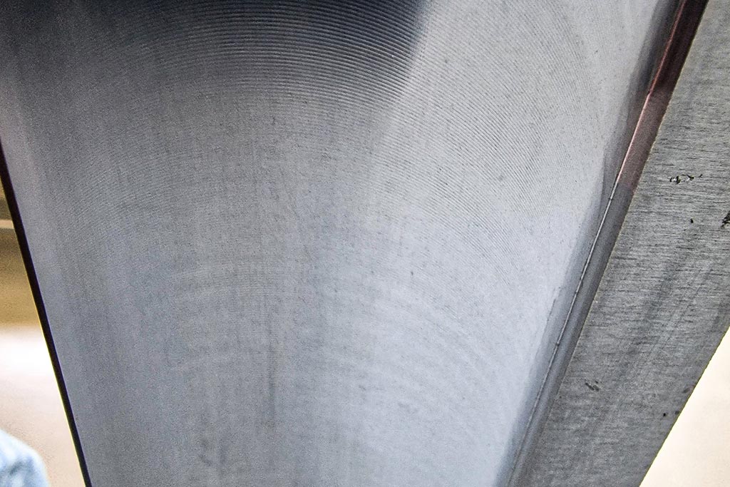
バッテリートレイを加工する場合、μm単位の精度は必要ありません。実際、自動車メーカーが塗布したシーラントの持ちをよくするためには、表面にある程度の粗さが必要です。ただうねりが大きすぎてはいけません。テストではフライスカッターを限界を超えるまで動かし、比較的薄い部品のビビリ跡がどの点まで許容範囲内に収まっているかを調べました。
切削データと位置決めが鍵
「ロボット加工の核心は、工具、治具、ロボットの相互作用です」とノルベルト・マイヤー氏は説明します。剛性は加工における基本的な問題です。ロボットアームが伸びれば伸びるほど、加工は不安定になります。そのためKADIAは様々な切削データをテストするだけでなく、ワークの前や横などのロボットの様々な位置もテストします。
このケースでは、主軸回転数11,000 rpmでの最適な切削データは、送り0.16 m/s、材料除去率0.5 mmであるとパートナーは判断しました。Fly Cutterは非常に優れた表面品質を確実に実現しました。KADIA社はこのテストデータをカスタムマシンのコンセプトに組み込みました。このためメーカーは、1つのセルに3台のロボットを使用することが、連続生産において最もコスト効率の良いソリューションになると判断しました。2台が前面加工を分担し、3台目が背面加工を行います。切削データに加え、KADIA社 は加工ステップの所要時間と達成可能なサイクルタイムを顧客に提供します。従って大型バッテリートレイのバリ取りには約80秒かかります。「ロボット加工では、このような切削データのプロセス情報はCNCマシンのように標準的なものではありません。ロボットの位置によって、同じデータでも異なる結果が得られます。」とヤニック・ヴァイス氏は話します。
KADIAとMAPALは、この好結果を受け、さらに協力関係を深めたいと考えています。様々な加工プロセスに対する更なるテストが既に計画されています。

Contact
Kathrin Rehor Public Relations Kathrin.Rehor@mapal.com Phone: +49 7361 585 3342