01.07.2019
Electric motor housings reliably enter large-scale production
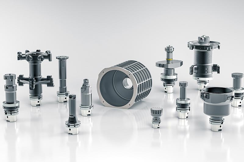
MAPAL provides innovative solutions for machining tasks
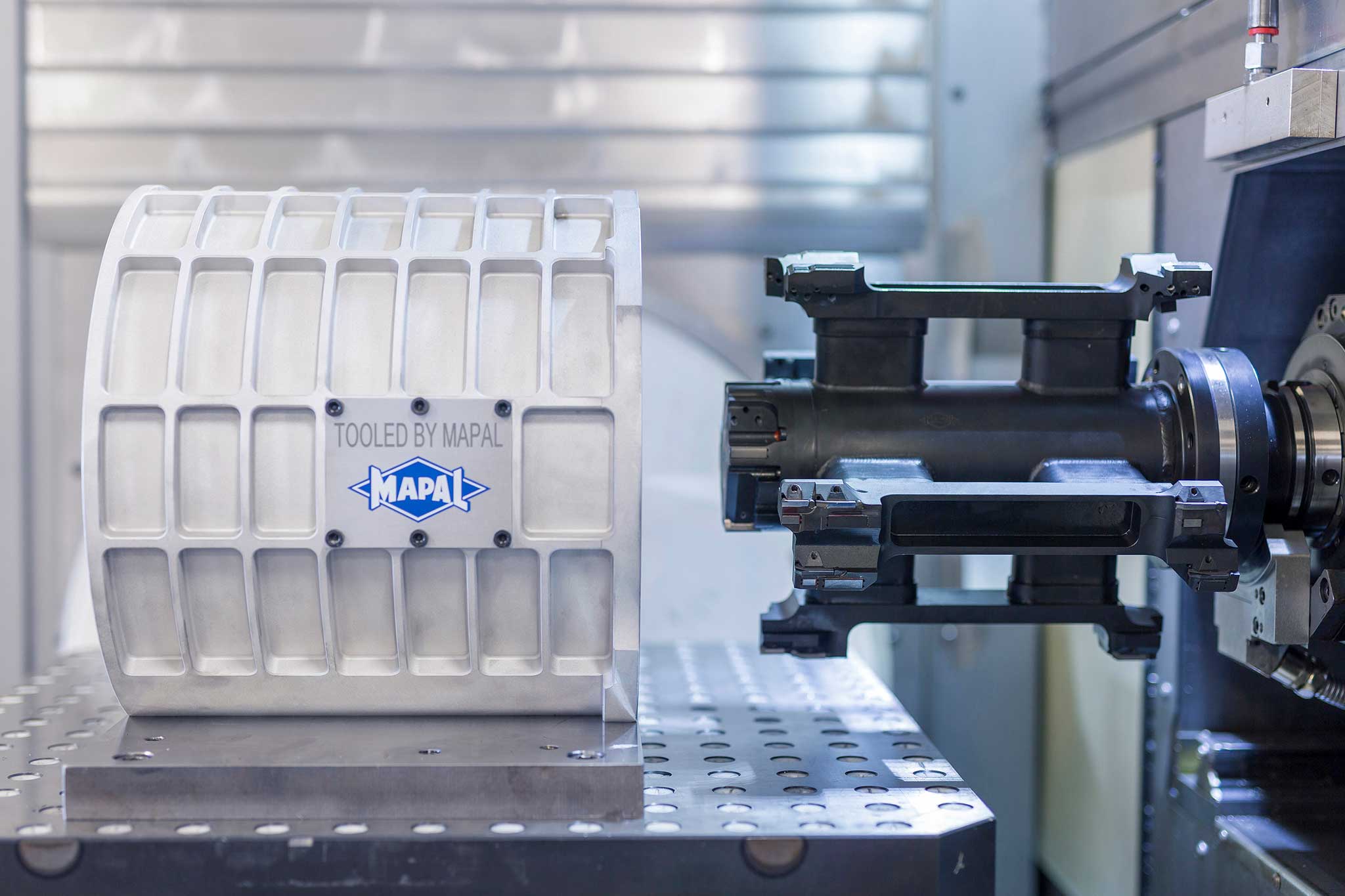
The number of vehicles with electric drives being produced is increasing alongside the importance of electric mobility. Although electric motors per se are nothing new, the automotive industry is currently entering uncharted waters in terms of both their use as means of propulsion for vehicles and their large-scale series production. Being a technology partner to its customers, MAPAL has devised a number of innovative machining systems, including some for the complex machining of electric motor housings.
The development of electric motors is clearly moving towards integration. Modern designs encase the electric motor, power electronics and gearbox in one central housing. When used as drive systems in vehicles, electric motors need to maintain their performance across a wide range of temperatures. Weight and efficiency play a major role. Highly automated, large-volume production that is as cost-effective as possible is another factor in the automotive industry.
Scalability of the requirements
How the machining approach affects tool design
Due to their bell-like shape, the thin-walled electric motor housings are prone to natural oscillation. For this reason, and because of casting-related stresses in the part, particular attention needs to be paid to the clamping setup and the various machining operations. During clamping setup for the part, it should be ensured that the radial forces are low so that the eventual outcome of machining, especially the cylindrical form, is not negatively affected.
Whereas the radial stock removal at the bore entrance is roughly 0.5 mm, the draft angles caused by casting result in material build-up measuring up to 13 mm in diameter forming at the bottom of the bore. This results in significant machining forces acting on the part and the tool, and these need to be taken into account in process and tool design.
Moment of tilt: a limiting factor
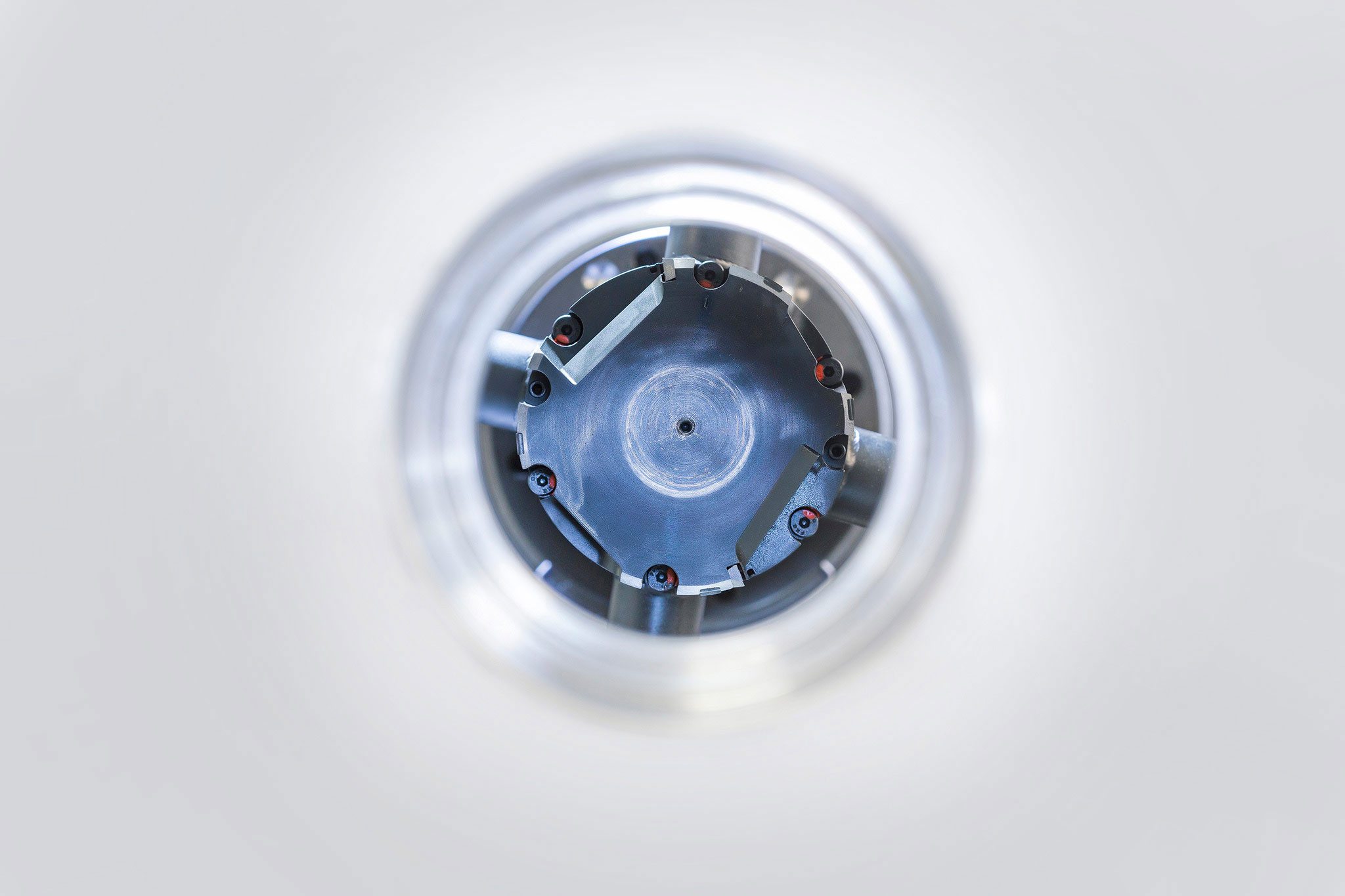
It is not unusual for stator bores to measure up to 300 mm in diameter. Machining this type of bore cost-effectively therefore calls for large tool diameters and long tool projection lengths. At such proportions, both the weight of the tool and its moment of tilt have a decisive impact on the machining process and can be limited by the requirements of machine tool and tool gripper. The tools should therefore be made as lightweight as possible.
One possible means of reduce weight and moment of tilt comes in the form of special tool designs, for example with innovative, additive manufacturing methods and the resulting ultra-lightweight designs. This not only enables customisable cooling channel design, but also allows enormous amounts of weight to be saved as a result of the geometric freedom that it opens up and the option to have hollow interiors.
Multi-machine approach recommended
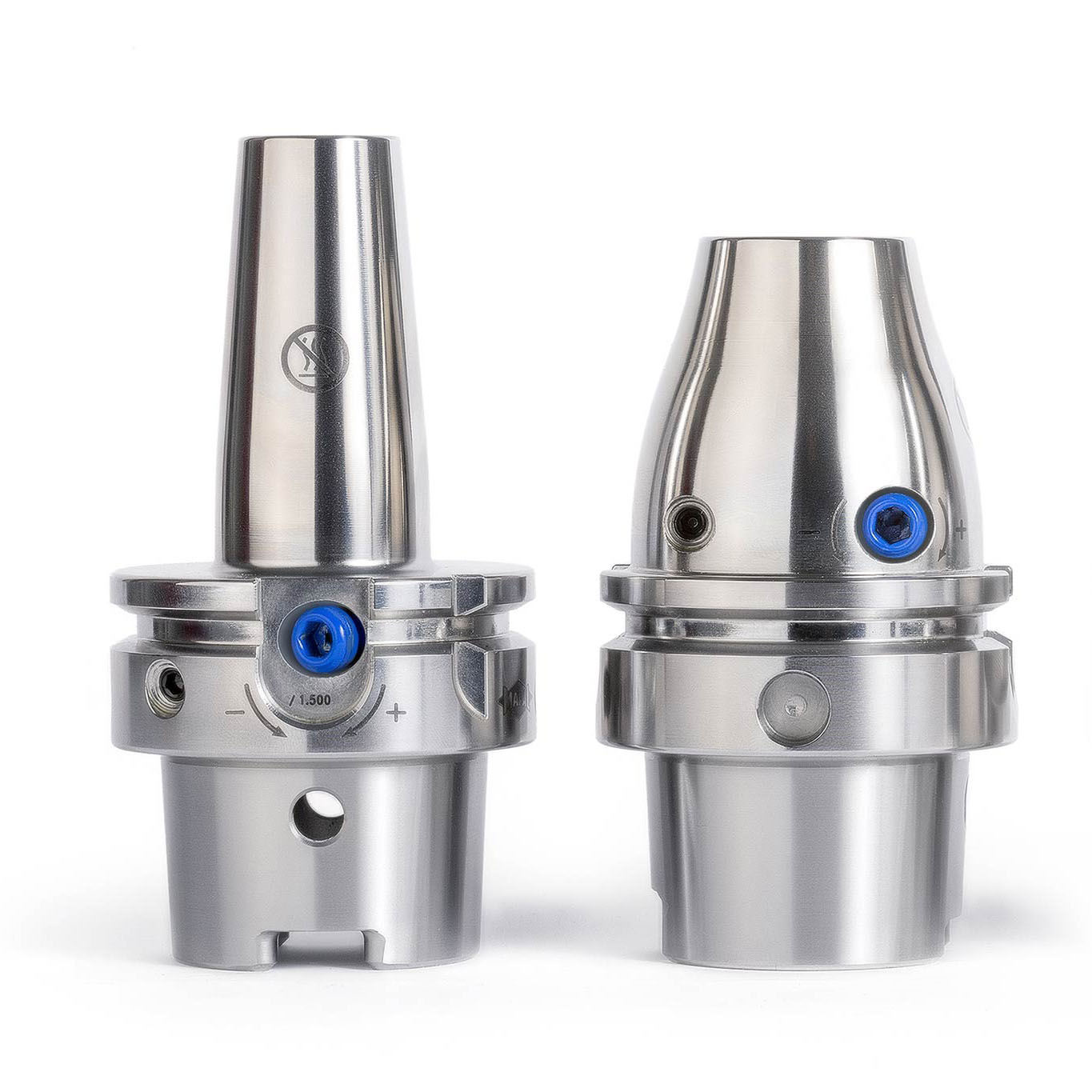
Thanks to the weight savings, it is possible to devise machining approaches for smaller machine connections, such as the HSK-A63. After all, only comparably low-weight tools with large diameters can be machined on less powerful equipment. Meanwhile, to make it easier to machine large diameters on machining centres with smaller tool connections, it is possible to reduce the number of teeth on the tool and thus the machining volume or the cutting torque. However, that comes at the expense of cycle time.
These options are particularly important because most of the existing machining centres in the automotive industry are fitted with HSK-A63 connections. One way of meeting the new requirements for parts for electric vehicles is to retrofit existing machine pools accordingly. A multi-machine approach is recommended for many machining processes. With smaller spindles, it is possible to work more flexibly and up to 15% more quickly than with HSK-A100 spindles. In ideal cases, machining centres with HSK-A63 connections should be used for all-round machining; for machining stator bores, however, machines with HSK-A100 connections are preferred. In each case, the connection on the machine side has a fundamental impact on tool design. That is because the number of teeth on the tool in question is chosen on the basis of the maximum possible torque and cutting power. As a general rule, the greater the number of teeth, the shorter the cycle times and the more powerful the machine and spindle need to be.
Requirements to the machining process
Machining of the housing is ultimately subject to tight tolerances with regard to
- the concentricity of the bearing and stator bores,
- the perpendicularity of the bores to the reference surface
- the roundness and cylindrical form of the stator bore and bearing seat.
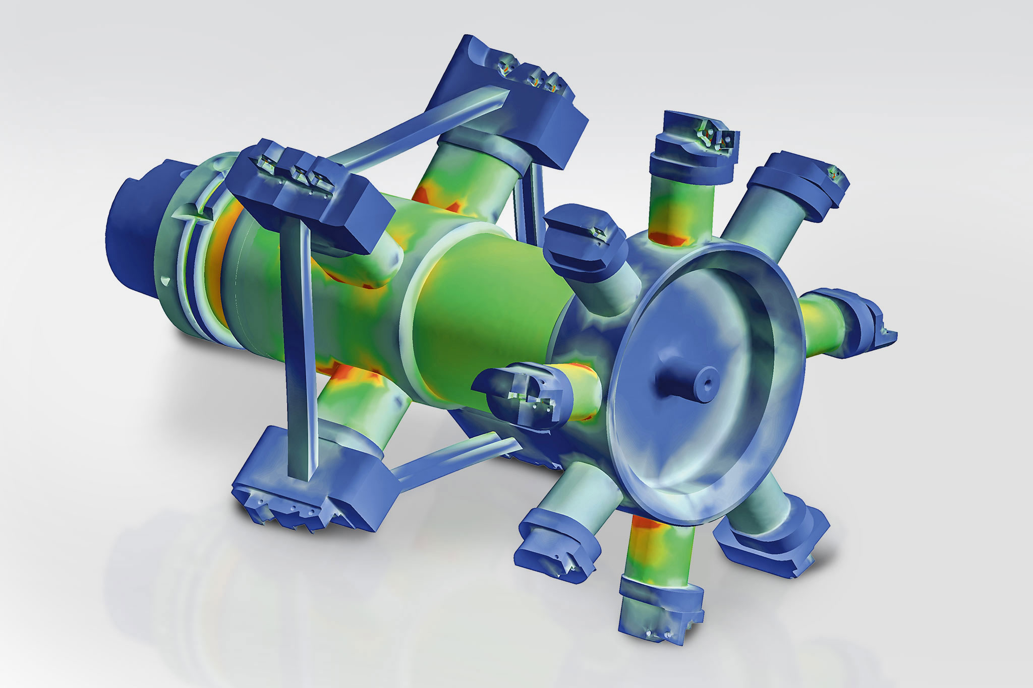
In addition to the tolerances, the Al-Si alloys usually used for electric motor housings impose particular requirements on the machining process. Depending on the composition, machining these alloys can sometimes produce very long chips. However, these are undesirable for any machining process and must be avoided as they may result in wear on the part and tool as well as an increase in torque or the temperature of the part. The temperature of the chips is usually in excess of 100 degrees Celsius, and the heat needs to be extracted along with the chips. To meet this requirement reliably, MAPAL has used the finite element method (FEM) to develop special chip guiding stages and chip breaker geometries.
Tool design
Pre-machining: Vorbearbeitung: High material removal rate with economic machining values
In most cases, the machine tool is the critical factor in the design of the tool for pre-machining the stator bore. In the machining process that MAPAL recommends, the first choice is a boring tool with cartridges and PCD-tipped indexable inserts. This tool is that it achieves a high material removal rate very quickly and thus cost-effectively because it allows work at high cutting speeds and feed rates. However, using this tool requires a machine with high maximum torque and power to match.
If such a machine is not available, the alternative is to pre-mill the stator bore. MAPAL offers an ISO helix milling cutters with PCD-tipped indexable inserts for this very purpose. Although this tool can also be used to work with very high cutting speeds and feed rates, the machining time is much longer than it is with boring on account of the longer machining stroke.
Semi-finishing and finishing: Ensure highest precision
In designing the tool for semi-finishing, MAPAL also focuses on the torque and power of the machine. This stage of machining involves pre-machining the complex contour definition of the electric motor housing so that finishing the complete contour including chamfers and radial transitions is possible in one machining step. For this stage of machining, MAPAL recommends a precision boring tool with PCD-tipped ISO indexable inserts.
The final stage involves machining the stator bore to micron precision with a fine boring tool, also a welded design. The PCD-tipped indexable inserts are finely adjustable, which helps to maximise accuracy. The tool is fitted with guide pads to provide the best possible support in the bore.
Bearing bore: Challenge of mixed machining
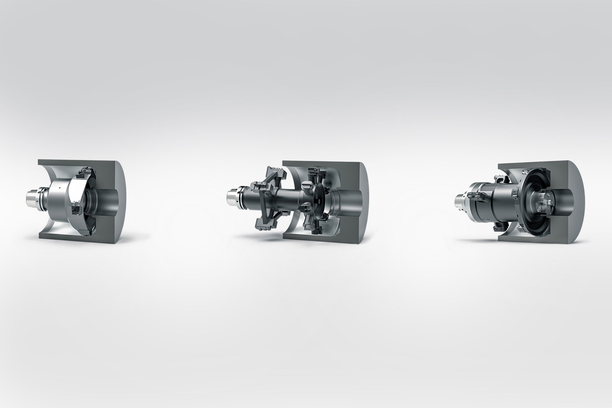
With some types of housings for electric motors, a steel bushing is pressed in for the bearing for the rotor shaft. The seat for the bushing is machined first and a bushing is pressed in the further course of the process. Because of the tough requirements for the concentricity of the bearing and stator bores, both bores are then fine machined with a combination tool. This involves one stage of the tool being used to machine the steel bushing and the rest to machine the stator bore out of aluminium at the same time. This is referred to as mixed machining and presents tool manufacturers with a number of challenges. Firstly, the steel chips need to be kept reliably away from the aluminium area. Otherwise, there is a considerable risk of damage to the surfaces of the component and the PCD guide pads on the tool. And secondly, the two materials differ in a fundamental way and have to be treated differently – in the choice of cutting speeds or the estimated end of the tool life.
A special chip guiding stage, the appropriate coolant supply and open chip spaces of the MAPAL machining solution ensure that the steel chips are reliably conveyed forwards. The aluminium chips, however, are routed backwards by means of a specially designed flushing mechanism. The MAPAL tool is also fitted with a protective plate that ensures that the steel chips are kept in the front area (see picture below, tool 3).
But how to work with the differing cutting speeds and tool lives? The specialists recommend 800 m/min for machining aluminium and 200 m/min for steel. And whereas PCD-tipped cutting edges can be used to machine aluminium on 6,000 to 8,000 aluminium parts, the tool life of the cutting edges, usually Cermet, for machining steel is at 250 to 300 parts. Indexable inserts are the solution in this case. Both insert types can be replaced on-site and can be fully used to the end of the respective tool lives.
Machining options for deep bores with large diameters: MAPAL solutions 90 percent faster