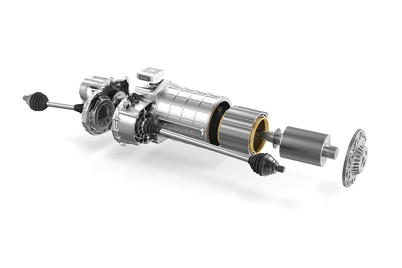
Electrified drives
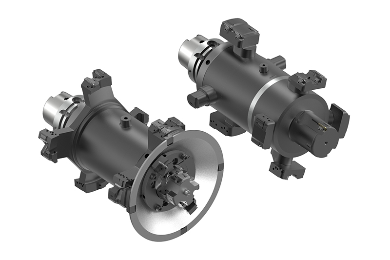
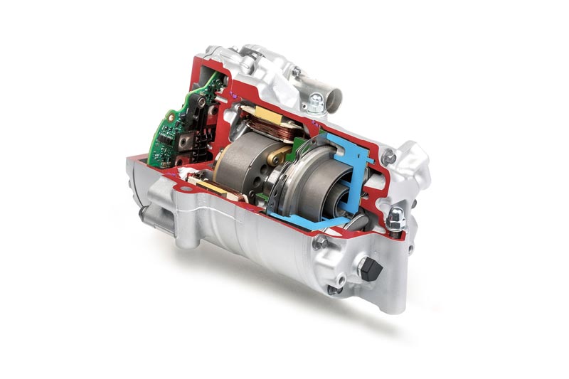
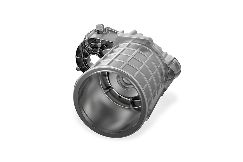
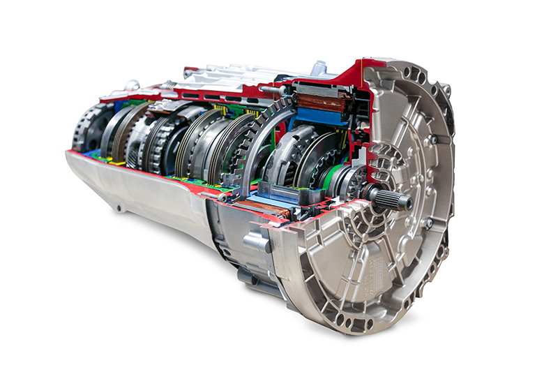
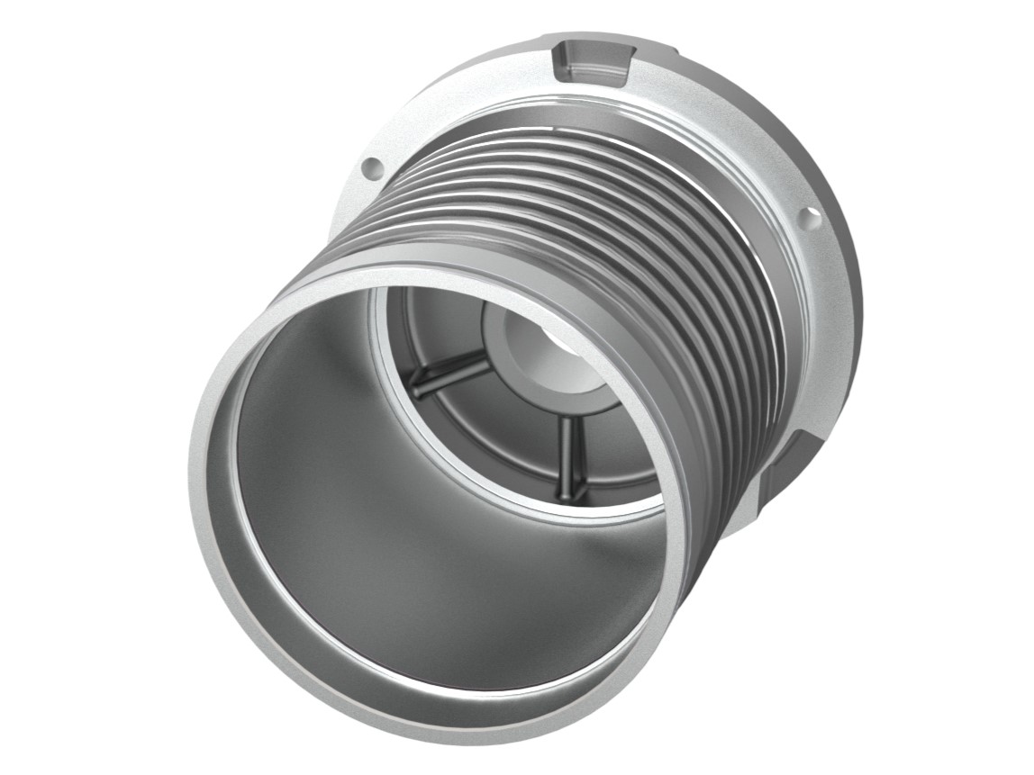
Automobile manufacturers and suppliers are facing new challenges when it comes to components for electric motors. The example of the housing of an electric motor shows how big these challenges are: Compared to a transmission housing, this has to be manufactured within significantly tighter tolerances, since the accuracy has a decisive influence on the efficiency of the motor.
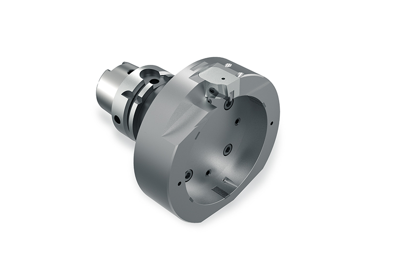
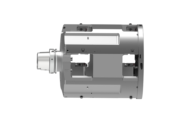
In addition, due to the special structure, such as integrated cooling channels, the electric motor housing is usually significantly thinner than a transmission housing. In addition, bearing bushes made of steel materials are pressed into some of these housings. Special protection shields in the tool ensure that steel chips do not come into contact with the aluminium surfaces during processing and damage them.
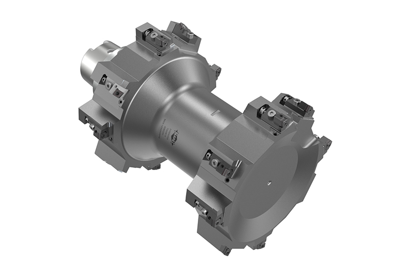
Machining requirements and features of different housing types
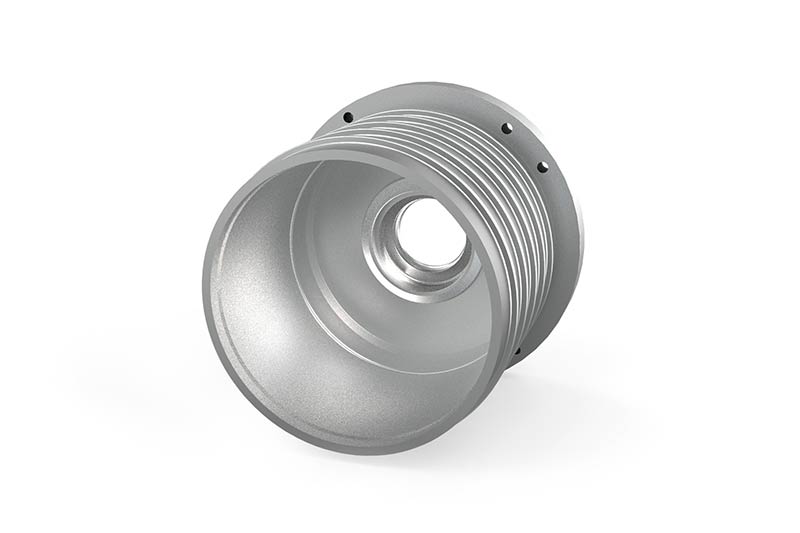
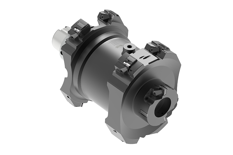
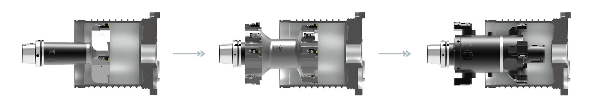
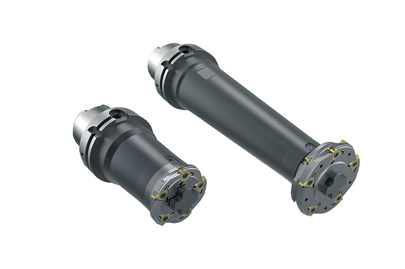
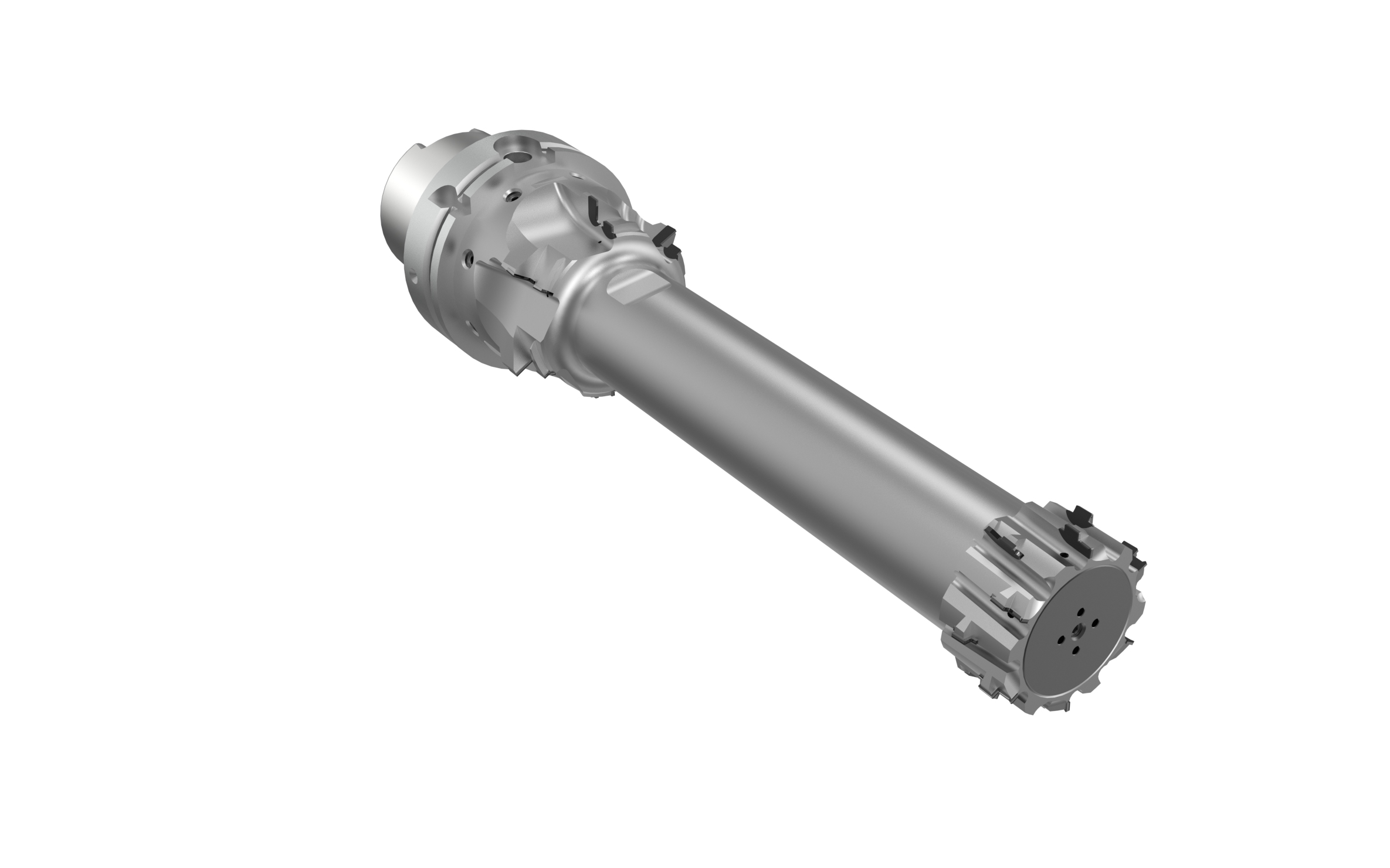
Basic procedure for machining of stator housings
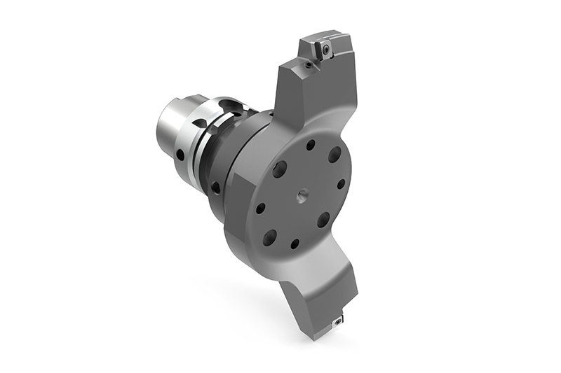
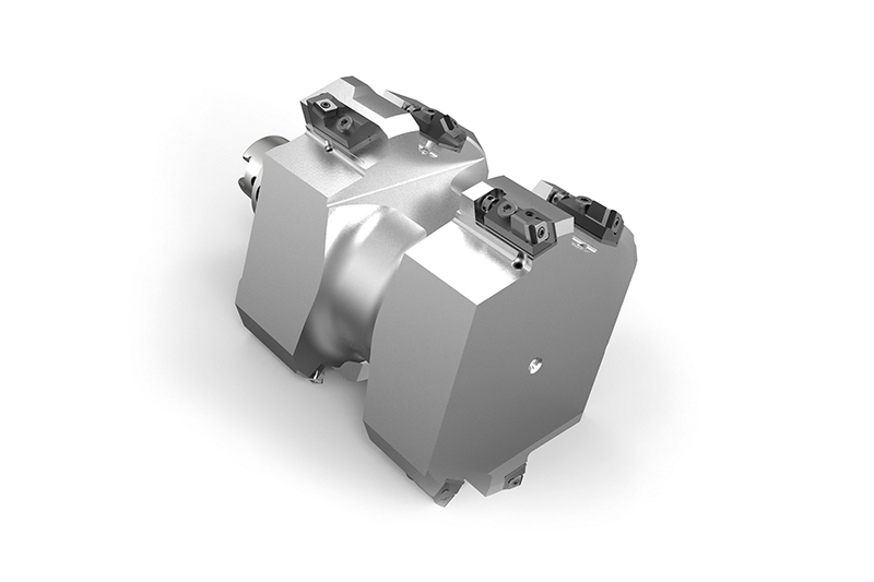
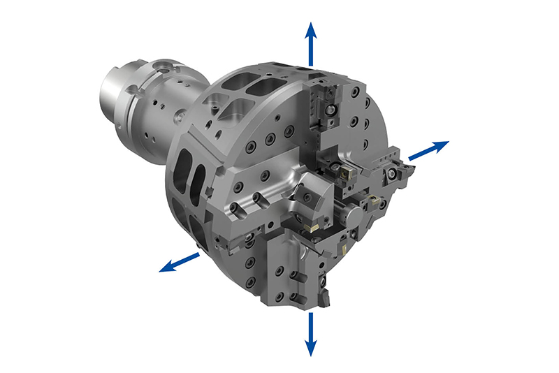
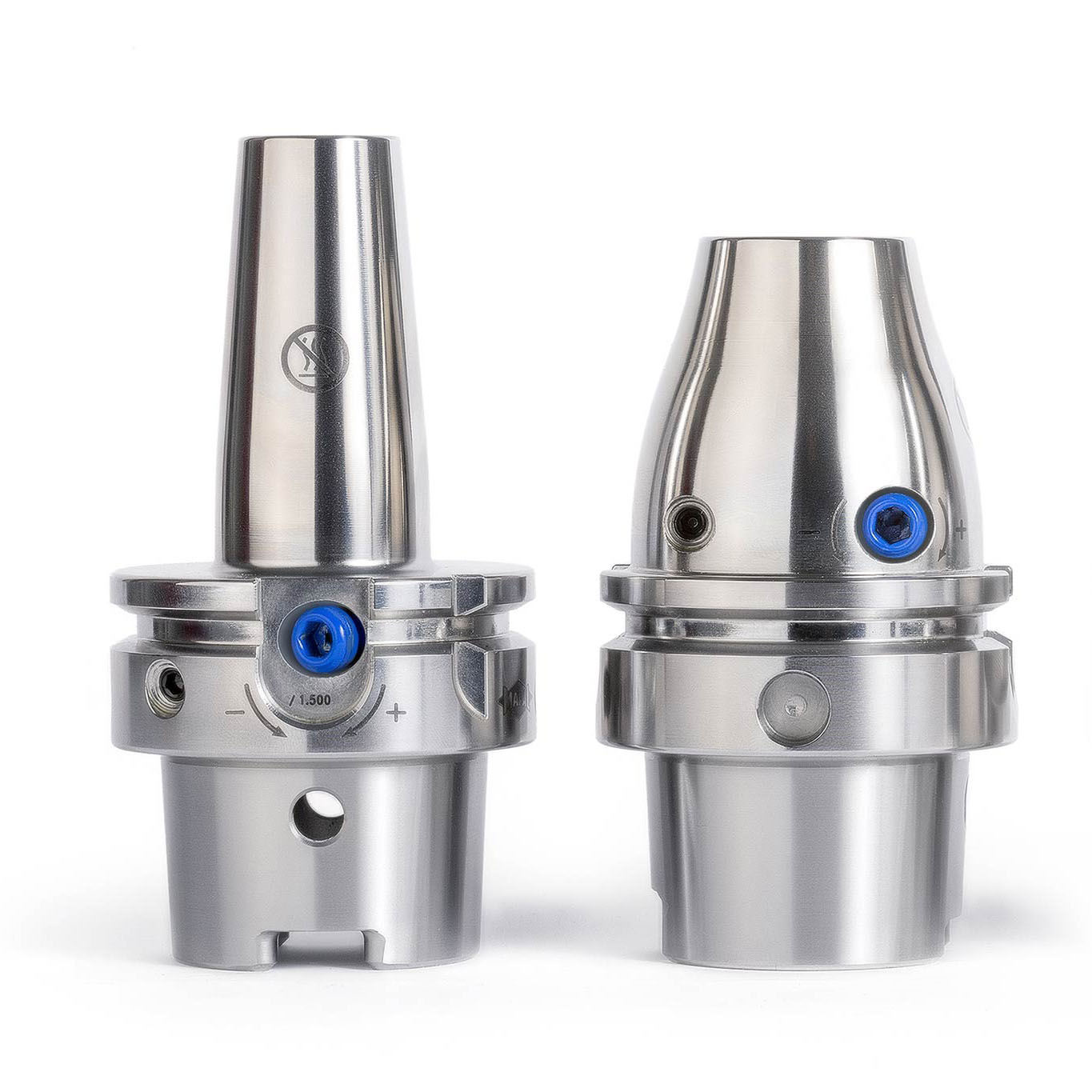
The machining process as well as the tools are designed individually depending on themeasurement situation, machine park and clamping setup. In this way, the cutting forces
applied to the component are kept as low as possible. The machining of the stator bore is divided into 3 steps: Pre-machining, Semi-finish machining and Finish machining.
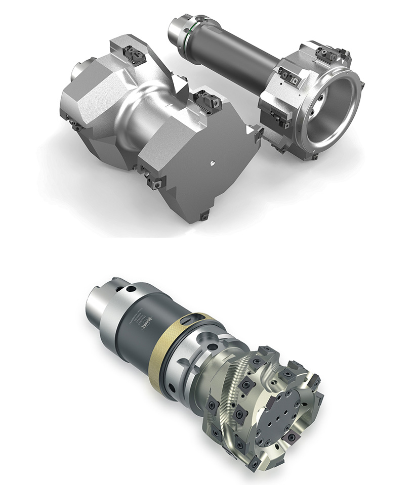
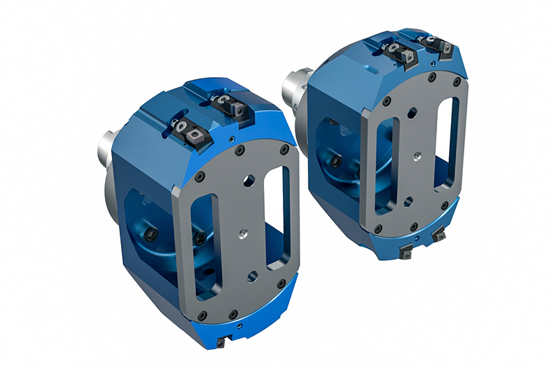
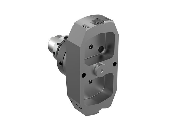
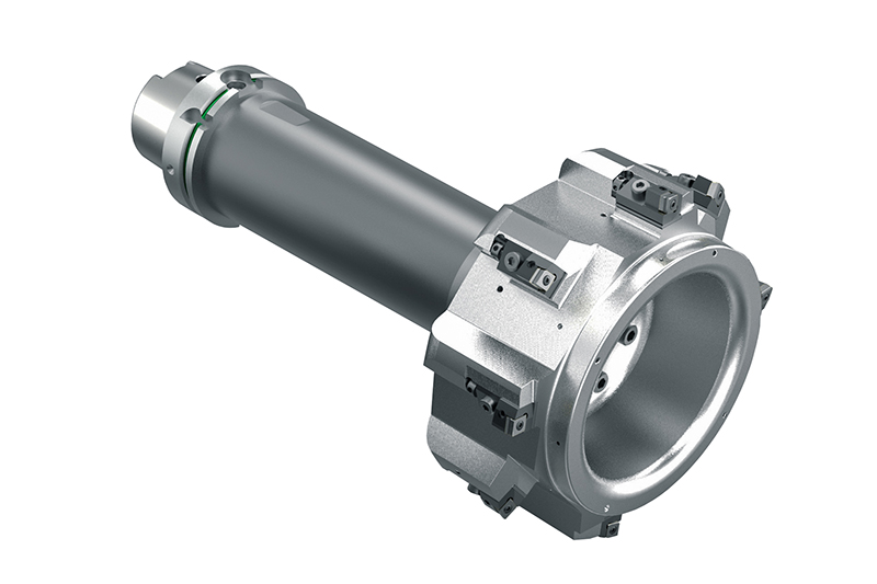
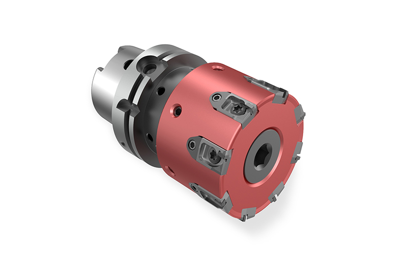
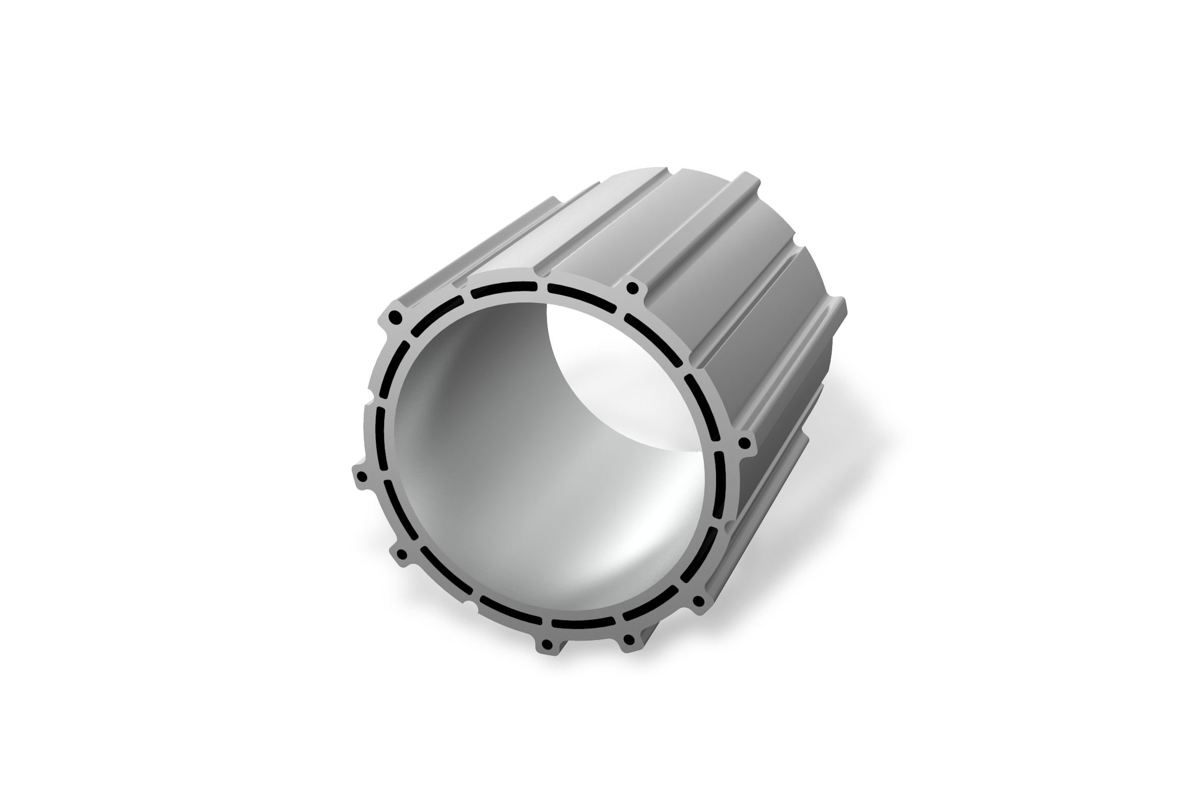
Außenbearbeitung von Statorgehäusen
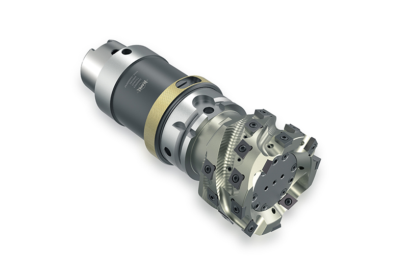
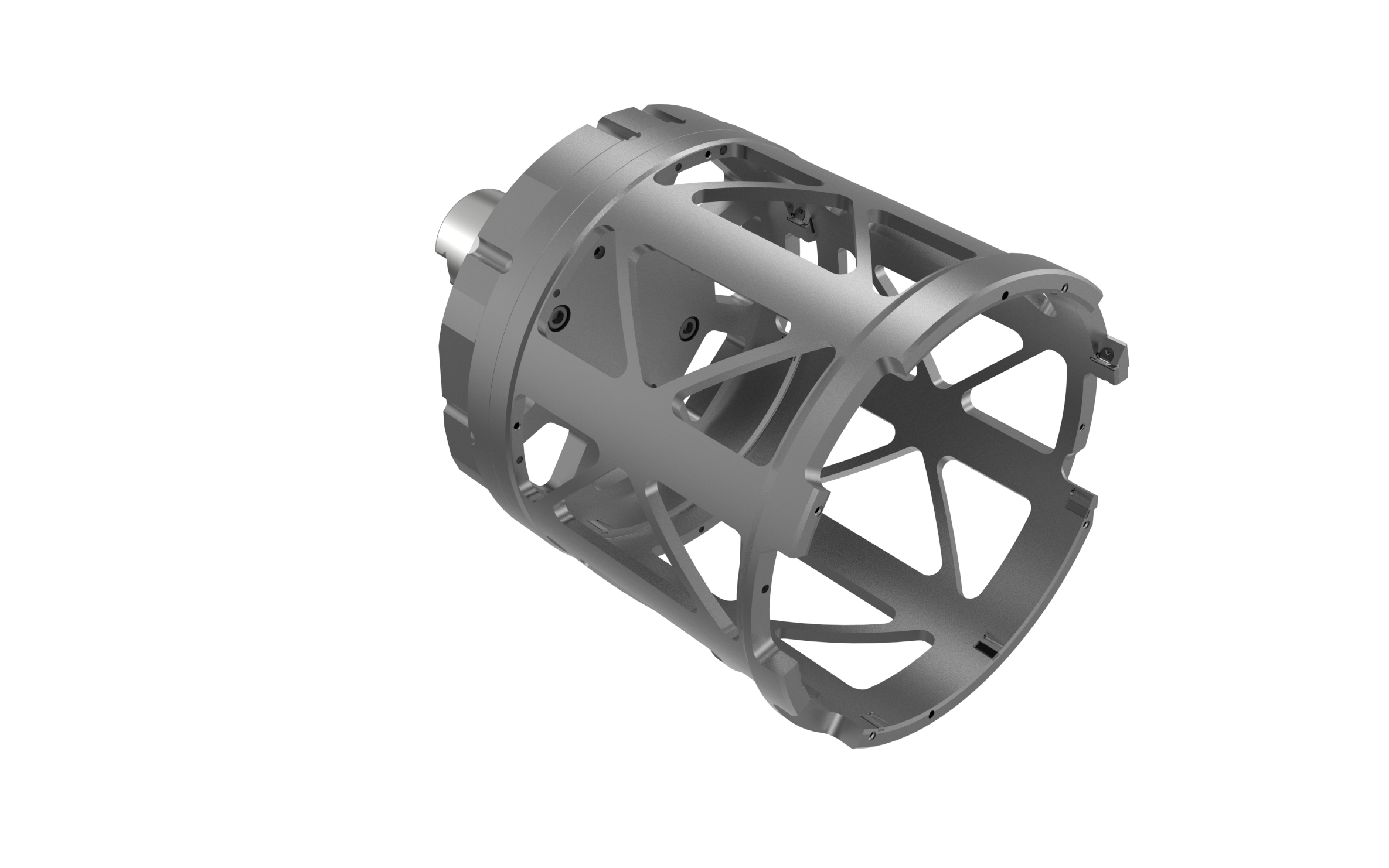
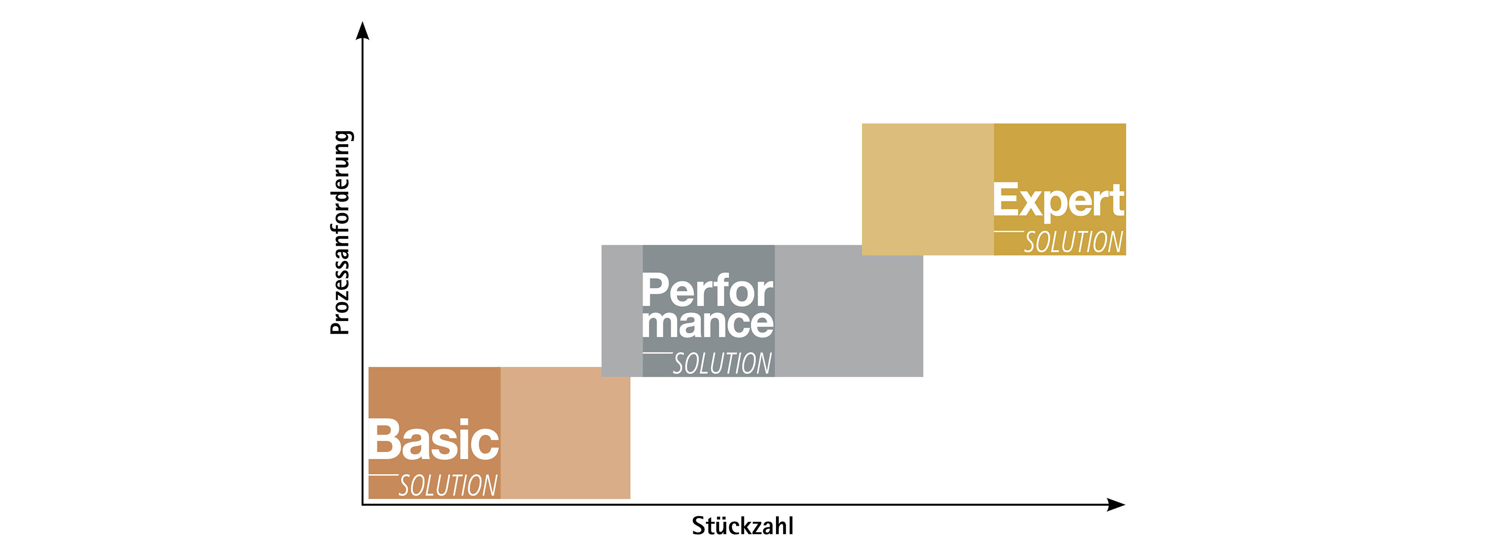
Machining solutions for...