01.01.2018
Dry Machining of Multilayer Composites in Aircraft Construction
MAPAL develop special tools for common combinations
The challenges that tool manufacturers have to overcome for optimum solutions in final assembly are diverse. Not only the different materials or the demand for the highest process reliability play a decisive role here, but also the cooling concept, narrow tolerance specifications and the machine used. MAPAL has been researching intensively into these challenges and has brought appropriate tool concepts onto the market. This includes the reliable dry machining of material combinations such as CFRP/aluminium or different aluminium alloys.

Materials that are both high-strength and light are of vital importance in the aerospace sector. Thanks to new material combinations, the weight can be further reduced, strength and corrosion resistance increased and assembly can be simplified by means of an integrated design. While structural parts made of aluminium, titanium or high-strength steels are machined on machining centres or portal machines, parts in final assembly are mostly machined by hand-held machines, drill feed units or robots.
The requirements for tool manufacturers and tools for final assembly therefore differ significantly from those for part manufacturing. While machined parts in part manufacturing have a value of around 1,000 to 50,000 Euros, parts in final assembly, depending on the assembly progress, are significantly more cost-intensive with a value of around 50,000 to 2 million Euros. Faulty machining must either be manually reworked, which is time-consuming and expensive, or the parts have to be completely replaced. For this reason, the suppliers for final assembly must be carefully chosen.
Challenges for tool manufacturers in final assembly
State-of-the-art: Manufacturing bores for rivet connections
Aircraft manufacturers use rivet connections for connecting the outer skin to the structural parts underneath. For this purpose, innumerable bores are drilled. To achieve the lowest resistance to the airstream as possible (low cW value), the rivet heads are countersunk in the outer skin. For this, an additional countersinking must be added to the bore entrance. In the past, a process with up to four individual machining steps was often required (drilling from the solid, boring, reaming, countersinking).
Today machining in just one step, where bore and countersink are realised in one process, is state of the art. Only in this way was automatic machining using robots possible. Previously this type of machining was realised with minimum quantity lubrication (MQL). After machining, the parts had to be disassembled, cleaned and remounted. In addition the cooling medium got inside the aircraft where further assembly steps were taking place at the same time. The demand for tools for dry machining different composite workpiece materials
was the consequence.
Call for dry machining
One-step processing
In contrast to a multi-stage drilling process, the combination tool must undertake all work steps (drilling, boring, reaming and countersinking) during machining and bore the rivet connection in one step. In this way, both the position of the bore and the alignment between the cylindrical part of the bore and the countersinking are ensured. Angular errors or offset that can occur with multi-stage operations are therefore excluded.
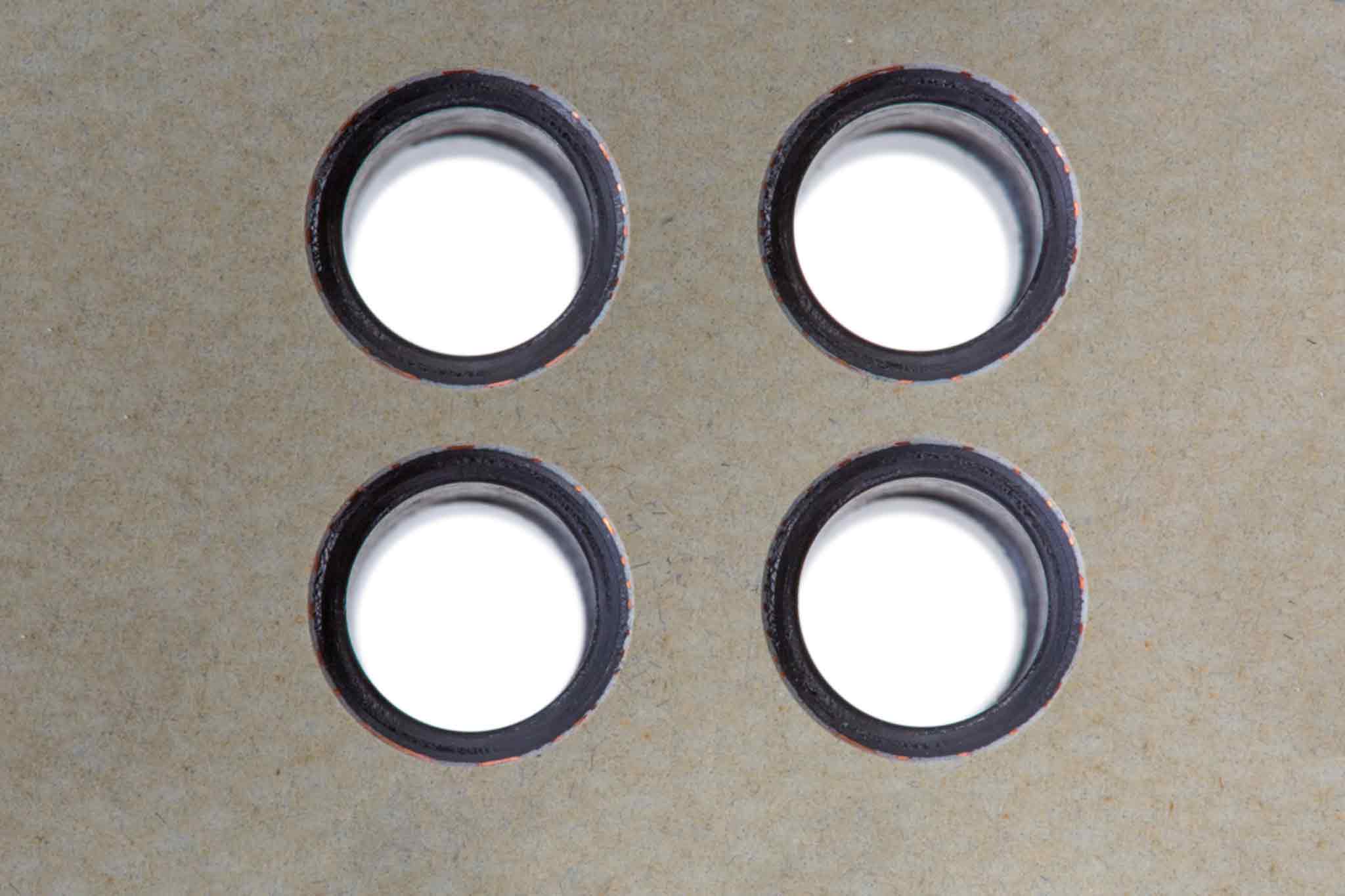
Together with other quality characteristics of the machining result such as diameter, transition radius and countersinking angle, the burr at the bore outlet plays an important role. If a burr has formed at the bore outlet for multi-stage bore machining that was manually executed, it can be removed without great effort with the aid of a countersink. If the process is automated in only one step, manual deburring is not possible. For this reason, the relevant tool must be able to drill virtually burr-free. Aircraft manufacturers usually specify a maximum burr height of 0.1 mm. In addition to the burrs at the bore outlet, the interlaminar burrs between the layers can arise. If they form, the multilayer composite must be dismantled at the end of the drilling operation to remove the interlaminar burrs. Dismantling is time consuming and cost-intensive and so these burrs must also be avoided.
Consequences of the machining concept
The machine concept significantly affects the tool geometry. CNC applications on machining centres or portal machines are characterised by a high rigidity and stable machine control. As a result, the tool is very well guided in the bore. Applications with drill feed units, robots or hand-held machines are less stable and require tools with additional stabilising features for high accuracies.
Another special feature of drill feed units are the so-called “nose pieces”, also called guide bushes. The chips are removed above the tool through the long and narrow guide bushes up to a suction channel that is located at the end of the guide bush. To be able to remove the chips, long chip spaces are required that must be correctly dimensioned and adapted.
The bores at the outer skin (fuselage and wing) are drilled with portal machines or robots. The inaccessible drill machining steps, mainly in final assembly, are then drilled with drill feed units or with hand-held drills.
Challenges of machining multilayer composite materials
Tools for machining composite materials
The outer skin and ribs of the latest generation of aircraft consist primarily of a composite made of CFRP and aluminium. In addition, combinations made of different aluminium alloys or CFRP titanium are often used in the aerospace sector. The dimensional accuracy of the bores in this composite material is crucial. The bore must feature exactly the same diameter in both materials of the respective combination. In principle drilling always takes place from the outside to the inside. For example, the bore entrance and the countersinking is in the outer skin that consists of CFRP when machining CFRP/ aluminium, and the bore outlet is in the structure underneath that is designed in aluminium. During the individual machining of CFRP and aluminium materials, the geometries of the tools as well as the cutting data are fundamentally different.
In contrast for CFRP-titanium combinations, tools with a cutting edge that is sufficiently stable are required to withstand the ductile titanium and simultaneously have the appropriate sharpness to cut the CFRP. Whether merely one boring process suffices to produce a bore or whether the bore must be subsequently reamed depends on the required bore tolerance for this material combination.
Tools for drilling composite materials made of different aluminium alloys, for example 7050 and 2024, do not need a wear-inhibiting coating. This is because the grades of aluminium used in aircraft construction contain no or very little silicon and can therefore be drilled virtually without wear. This multilayer composite is significantly different to composites that contain CFRP when machining.
Tools that are used for material combinations that contain CFRP are generally provided with a diamond layer. This counteracts the abrasion of the CFRP and enables long tool lives. Regrinding these tools is not possible as the diamond layer used has a very high hardness.
What has to be taken into account when designing the tools?
To ensure process reliability during machining, attention must be paid to the quality requirement, the material and the process for the design of the tool geometry. As the majority of bores in aircraft are produced with countersinking due to the rivets, the bore outlet is to be assessed more critically to exclude cost-intensive rework. Delamination and fibre projections must be prevented in CFRP material and burr formation in aluminium. Chip removal is also important for machining all individual materials as well as all composite materials.
If perfect chip removal is not ensured, the bore quality for dry drilling is significantly outside the required tolerances. However the biggest challenge for the development of a dry drill is the adaptation of the tool geometry to the unstable machining stable of the drill feed units in combination with cutting parameters and clamping systems (concentric collet).
Drilling/countersinking tool for machining aluminium/aluminium combinations
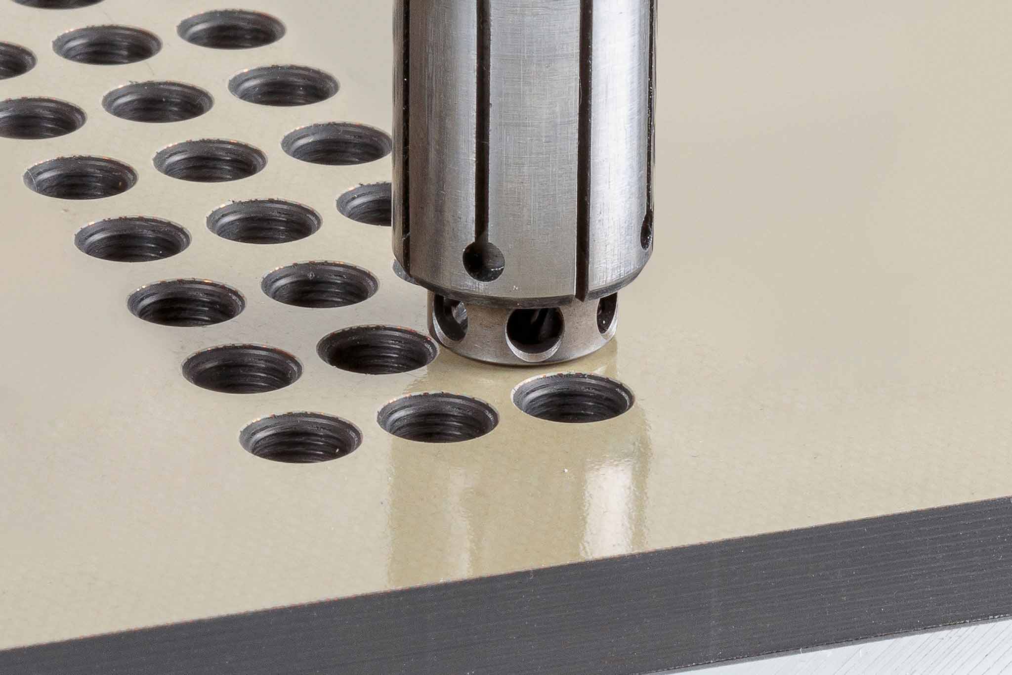
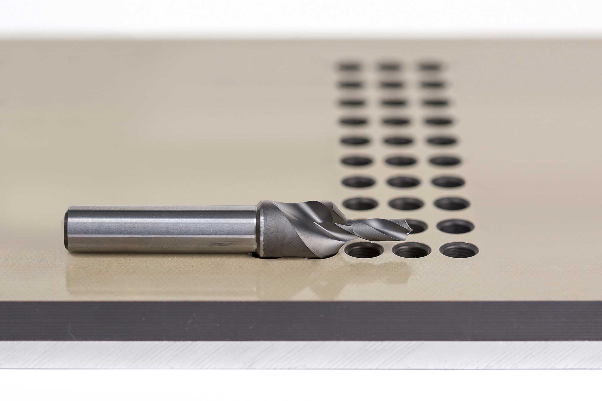
MAPAL has developed a drill with countersink step for dry machining composite materials made of different or the same aluminium alloys. Burr formation is kept as low as possible and an improved centring is achieved thanks to the special geometry features. The coating of the drill prevents the formation of a built-up edge at the cutting edge. Specially formed chip flutes ensure optimum chip removal. Air is used for cooling, preventing overheating of both the cutting edge and the aluminium and hence burr formation. The compressed air is also used to blow out the chips.
At one aircraft manufacturer, the drill is used i.a. for the bores on the longitudinal seam in the rear main span. A spindle speed of 2,959 RPM and a feed of 0.154 mm are applied here. The drill with its diameter of 4.748 mm and a 100° countersink step reliably produces 1,600 bores before the bores no longer lie within the demanded tolerance of 4.73 - 4.805 mm.
Drilling/countersinking tools for machining CFRP/aluminium combinations
chips.

In use at an aircraft manufacturer: the drilling and countersinking tool for machining aluminum-aluminum combinations
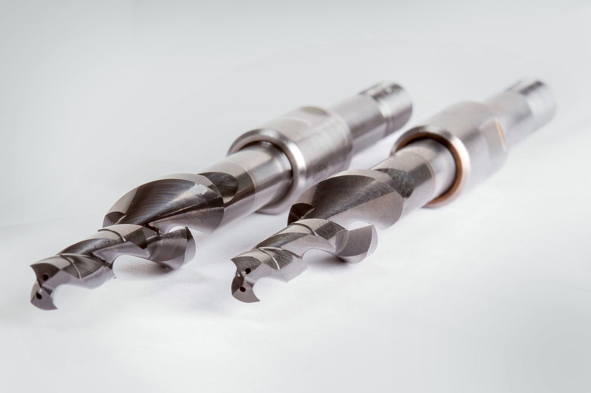
Drilling/countersinking tools for machining CFRP/aluminium combinations
To reliably dry machine composite materials made of CFRP and aluminium, MAPAL has also developed a drill with countersink step. The special geometry of the tool ensures that the heat caused by machining is not transferred to the part. In addition, neither part nor work environment is contaminated with coolant. The drill with two cutting edges made of solid carbide combines the properties of a drill for machining aluminium with those of a drill for CFRP machining. Reliable removal of the chips is ensured by the specially designed chip spaces. As CFRP is an extremely abrasive material, the drill is diamond-coated. This means that eight times the tool life is achieved compared with an uncoated drill.
The drilling/countersinking tool for dry machining CFRPaluminium combinations has been successfully used by customers. A spindle speed of 5,000 RPM and a feed of 0.1 mm are applied. The tool impresses not only with regard to process reliability, tool life and machining result, but also because of the steady boring process.
