01.09.2018
Schwingungsanfällige Strukturbauteile prozesssicher bearbeiten
Wie Kunden mit einer Komplettlösung von MAPAL anspruchsvolle Strukturbauteile wirtschaftlich und prozesssicher zerspanen.
Die besondere Herausforderung für Zerspaner bei der Bearbeitung dünnwandiger Bauteile ist, dass diese Bauteile konstruktionsbedingt sehr labil und anfällig für Schwingungen sind. Entsprechend anspruchsvoll sind Prozess- und Werkzeugauslegung. MAPAL bietet die Lösung zur Komplettbearbeitung.
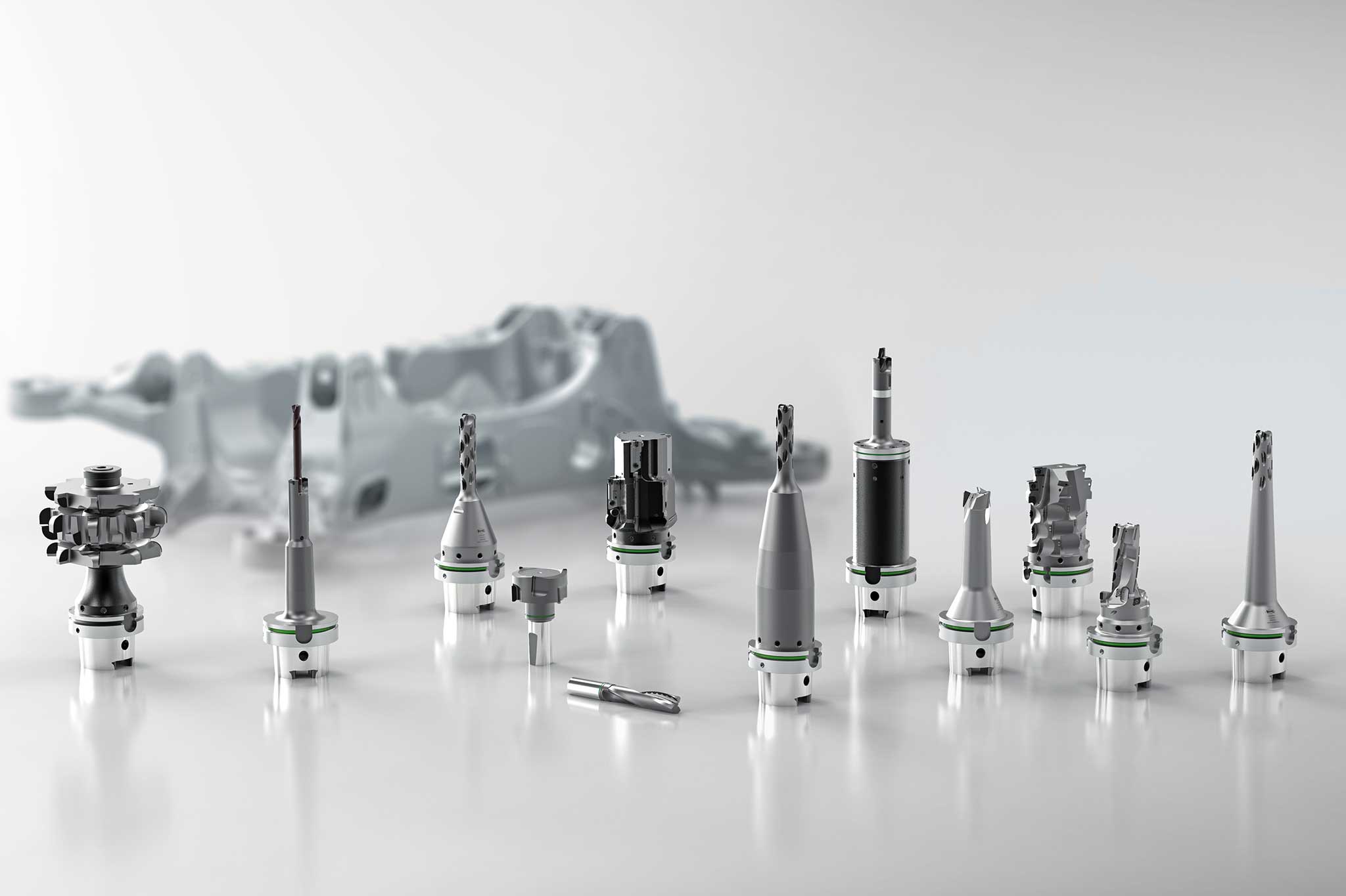
„Für unsere Kunden ist es wichtig, Bauteile möglichst in einer Aufspannung zu bearbeiten“, betont Leander Bolz, Vertriebsleiter PKD-Werkzeuge bei MAPAL. „Um dieser Forderung nachzukommen und möglichst alle zu bearbeitenden Bereiche für die Werkzeuge zugänglich zu machen, müssen Zerspaner allerdings Abstriche bei der Aufspannung machen. Das heißt in der Folge, dass das Werkstück nicht optimal abgestützt ist und zu Schwingungen neigt.“ Überdies stellen dünne Stege, Hohlräume und Unterbrechungen sowie stark schwankende Aufmaße des Gussrohlings spezielle Bedingungen dar. Bei großen Bauteilen mit vielen Bearbeitungen benötigen Zerspaner darüber hinaus eine große Anzahl an Werkzeugen. Leander Bolz: „Wir versuchen daher, wo immer möglich einzelne Bearbeitungsschritte zu Kombinationswerkzeugen zusammenzufassen. So reduzieren wir die Nebenzeiten und die Anzahl benötigter Werkzeugplätze.“
MAPAL greift auf ein umfassendes Prozessverständnis im Hinblick auf die Bearbeitung labiler Strukturbauteile zurück und ist so in der Lage, wirtschaftliche und sichere Prozesse umzusetzen. Dabei sind mehrere Ansatzpunkte von Bedeutung. Zunächst sind die Schnittwerte eine Stellschraube, über die Zerspaner während der Bearbeitung ein Aufschwingen vermeiden können. Dabei sind sowohl Schwingungen des Werkzeugs zu vermeiden, die zu Vibrationen und damit schlechten Standzeiten und Bearbeitungsergebnissen führen, als auch Schwingungen des Werkstücks. Letzteres würde ein Rückfedern des Bauteils gegen die Schneide nach sich ziehen und könnte Beschädigungen am Werkzeug verursachen. Die zweite wichtige Stellschraube in der Prozessauslegung ist die Betrachtung des Werkzeuggrundkörpers. Der Werkzeughersteller muss den Grundkörper entsprechend gestalten und das optimale Material auswählen, um Vibrationen zu reduzieren. Darüber hinaus sorgt eine intelligente Schneidenanordnung in Form und Lage dafür, die Zerspankräfte niedrig zu halten. Und schließlich bietet auch der Zerspanungsprozess selbst Möglichkeiten, schwingungsanfällige Bauteile sicher zu bearbeiten. Durch die Wahl alternativer Teilprozesse ergibt sich eine veränderte Kräfteverteilung, die die Prozesssicherheit erhöhen kann. Beispielsweise kann der Ersatz einer Vollbohroperation durch eine Zirkularfräsoperation den Prozess stabilisieren.
Angepasste Werkzeugausführungen machen Vibrationen beherrschbar
„Wir haben beispielsweise einen Zirkularfräser zum Plan- und Umfangsfräsen bei der Bearbeitung eines Fahrwerkbauteils eingesetzt, da wir dort stark mit Vibrationen zu kämpfen hatten“, erläutert Leander Bolz ein Beispiel eines erfolgreich adaptierten Werkzeugs für Strukturbauteile. Dazu haben die Experten des Werkzeugherstellers einen reduzierten Helixwinkel und eine geringe Zähnezahl für das Umfangsfräsen (Z=3) eingesetzt. Dadurch sind die Zerspankräfte reduziert und die Vibrationen beherrschbar. Die anschließende, besonders verschleißanfällige Planfrässtufe des Werkzeugs führt MAPAL konsequenterweise mit wirtschaftlichen ISO-Wendeschneidplatten aus. So können Kunden bei einer Eingriffsbreite von 6 mm und einer Schnitttiefe von 60 mm mit maximalen Schnittwerten fahren. Zusätzlich hat das Werkzeug eine Stirngeometrie mit Z=6 erhalten, um eine weitere Planfräsoperation auf dem Bauteil wirtschaftlich und in kurzer Taktzeit zu bearbeiten.
Schnittwerte:
- vf = 2.700 mm/min
- fz = 0,1 mm
- n = 9.900 min-1

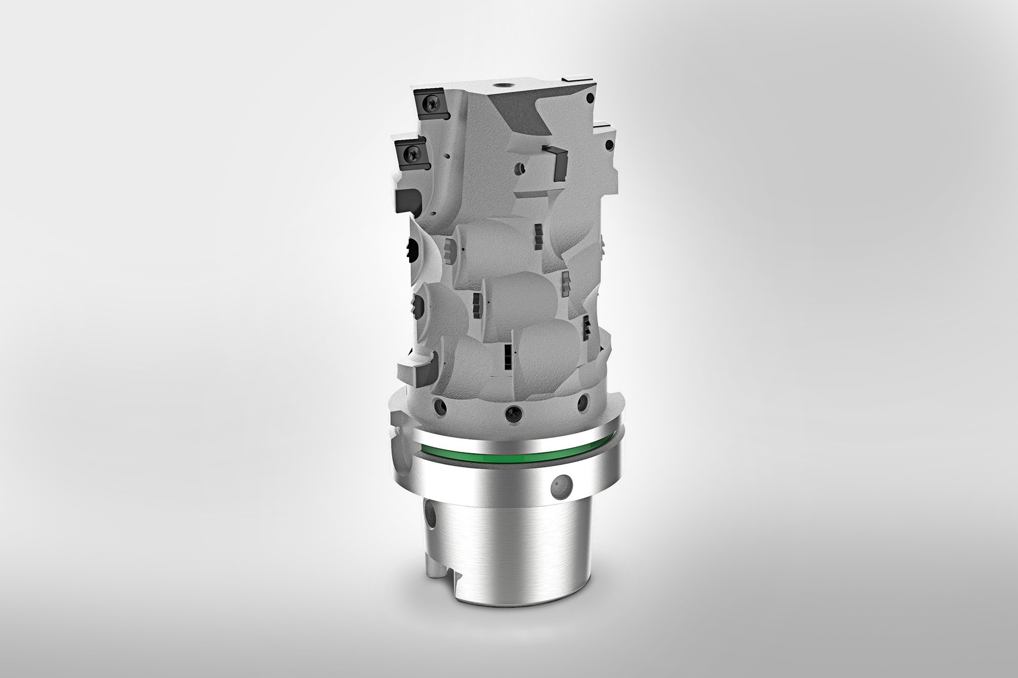
Ebenfalls bei der Bearbeitung eines Fahrwerkbauteils kommt ein angepasster Tauchfräser zum Einsatz. Das Werkzeug taucht halbschalig an einer Lasche ein und schneidet mit zunehmender Tiefe bis über das Zentrum. Eine optimierte Frontgeometrie und Spannutausführung, eine lastreduzierte Schneidenanordnung sowie die Integration von Schwingungsdämpfern in das eingesetzte Spannzeug halten die auftretenden Vibrationen gering und ermöglichen einen sicheren Prozess.
Schnittwerte:
- vf = 1.200 mm/min
- fz = 0,1 mm
- n = 4.500 min-1
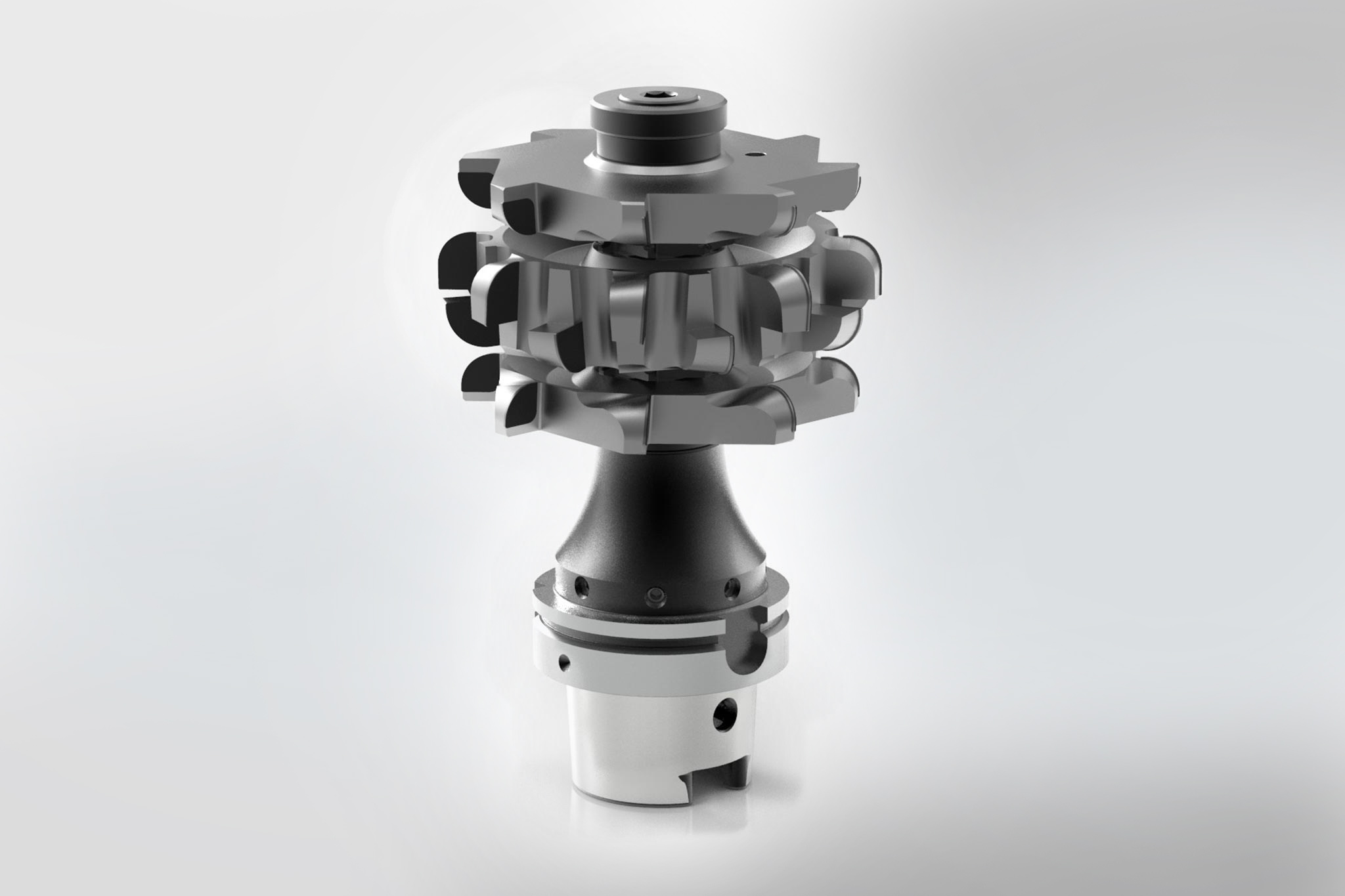
Ein Scheibenfräsersatz nutet simultan mehrere Stege und Kammern und bearbeitet die Planflächen fertig. Um den Fräsprozess ruhig zu halten und ein Verklemmen der Späne zu verhindern, haben die Werkzeugentwickler den Schneideneingriff speziell abgestimmt und eine Schnittaufteilung realisiert. Das Werkzeug bearbeitet sicher alle Bereiche in einer Zustellung, was aufgrund der Forderung nach hohen Taktzahlen von großer Bedeutung ist.
Schnittwerte:
- vf = 600 mm/min
- fz = 0,07 mm
- n = 1.500 min-1
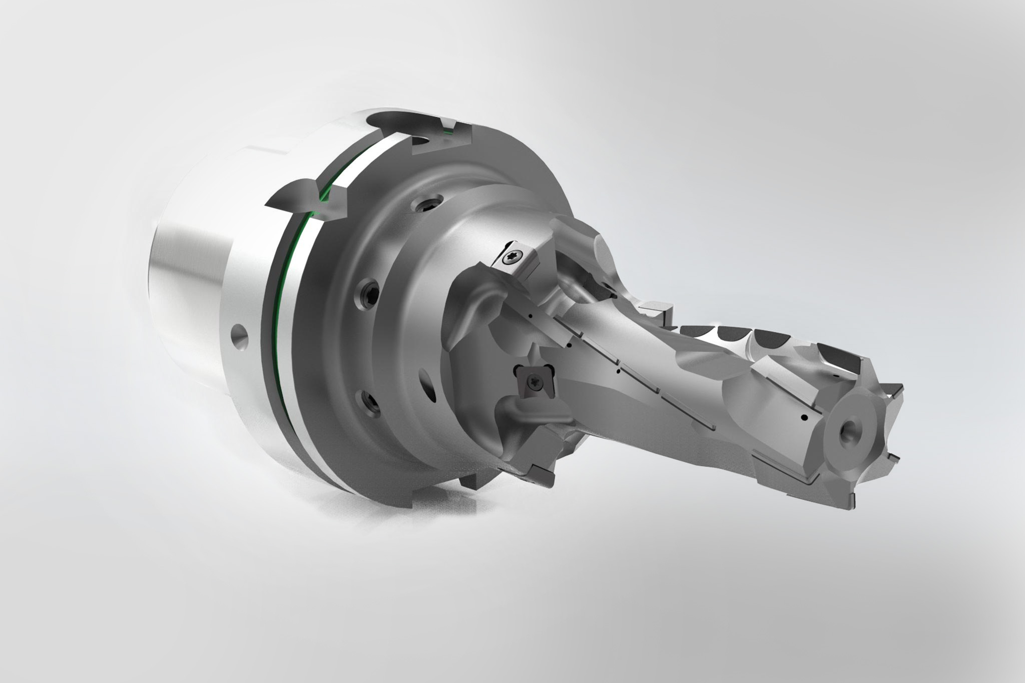
Ein besonders interessantes Werkzeug, das ein Kunde für das robotergestützte Einbringen von Befestigungsbohrungen einsetzt, nennt Bolz als letztes Beispiel: „Hier handelt es sich in mehrerlei Hinsicht um ein Kombinationswerkzeug. Wir haben hier fest gelötete PKD-Schneiden für lange Standzeiten und für die stark verschleißanfällige Bearbeitung auswechselbare ISO-Wendeschneidplatten untergebracht. Darüber hinaus kombiniert das Werkzeug die Vor- und Fertigbearbeitung. Und führt sowohl eine Bohr- als auch eine Fräsoperation durch.“
Schnittwerte Fräsen:
- fz = 0,1 mm
- n = 3.800 min-1
Schnittwerte Bohren:
- fz = 0,08 mm
- n = 480 min-1
Mit MAPAL zum sicheren Prozess