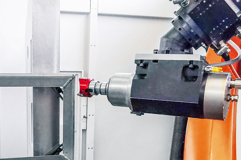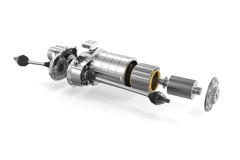
Gehäuse für die Energieversorgung
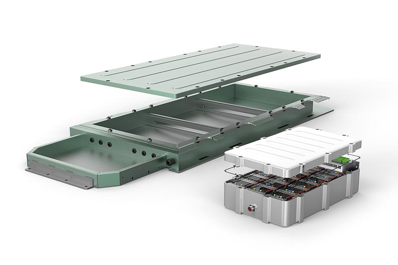
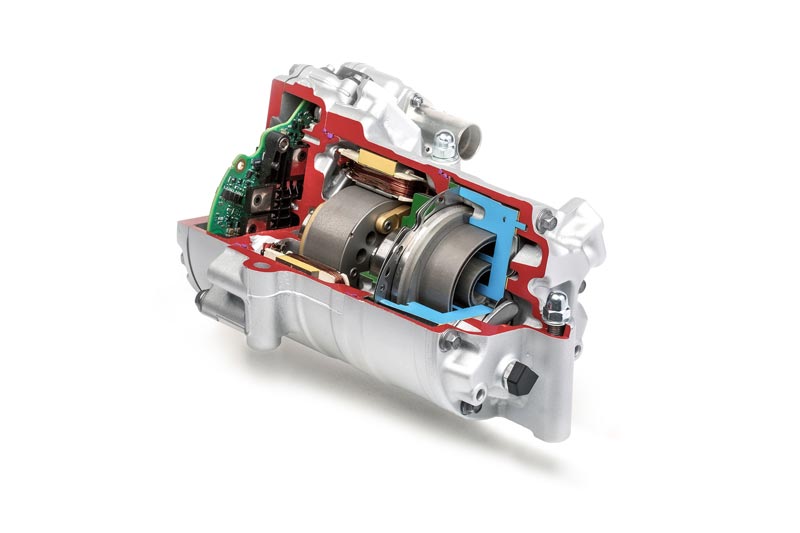
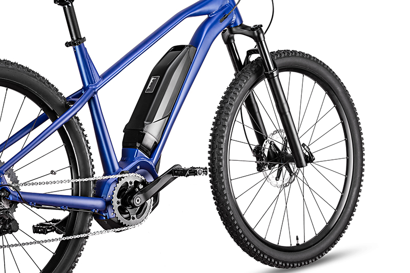
Für den Schutz elektronischer Bauteile, wie beispielsweise Batteriesystem oder Leistungselektronik, vor äußeren Umwelteinflüssen und zur Fixierung der Komponenten im Innenraum, um deren störungsfreie Funktion während des Fahrzeugbetriebes zu gewährleisten, werden unterschiedliche Gehäuse eingesetzt. Die Anforderungen an die Gehäuse sind abhängig vom elektronischen System und Antriebskonzept. Aktuell kommen unterschiedliche Werkstoffe und Fertigungsverfahren zum Einsatz.
MERKMALE
- Labile, dünnwandige Bauteile (vibrationsanfällig)
- Aufbau als gegossene Wanne oder als Rahmenkonstruktion aus Hohlprofilen
- Teilweise niedrig-siliziumhaltiges Aluminium
- Großflächig (2 x 3 m)
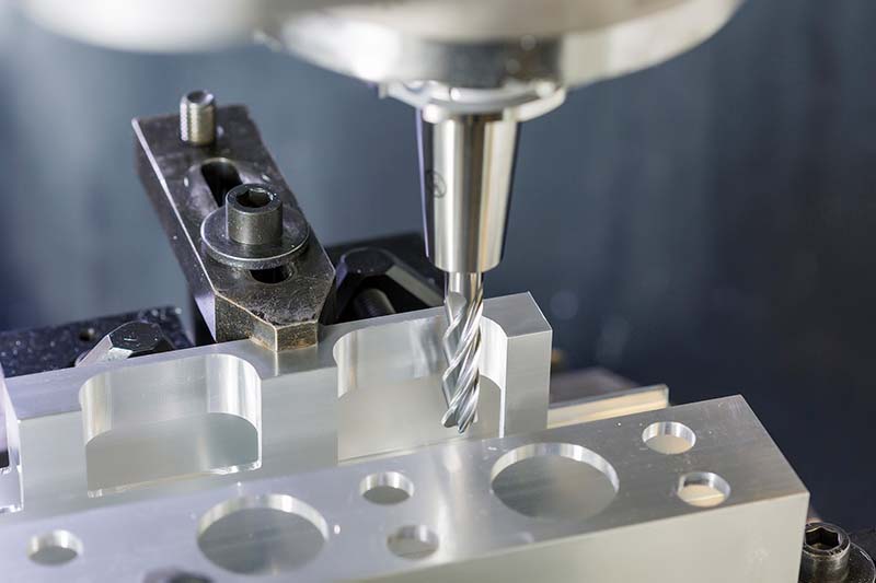
- Hauptsächlich Bohr- und Fräsoperationen und Gewinden
- Genauigkeits- und Oberflächenanforderungen bei Kabeldurchführungen und Kühlanschlüssen


Visão geral das ferramentas
-
 1 / 9
1 / 9Programa standard para a usinagem de componentes estruturais de alumínio
- Geometria de corte altamente positiva
- Forças de corte reduzidas
- Corte de baixa vibração
-
2 / 9
OptiMill-SPM-Rough
- Usinagem em desbaste com poucas vibrações e com maior profundidade de corte
-
3 / 9
OptiMill-SPM
- Ideal para a produção de aberturas de cavidades
- Modelo em metal duro integral ou com lâminas de PCD soldadas
-
4 / 9
OptiMill-SPM-Finish
- Acabamento de grandes profundidades em etapa única
- Forte desempenho em caso de emaranhamento elevado
-
5 / 9
Tritan-Drill-Alu
- Criação de furos centrais
- Três arestas de corte para as maiores taxas de avanço
- Maior precisão de posicionamento por meio da aresta de corte transversal autocentrante
-
6 / 9
MEGA-Drill-Alu
- Broca de metal duro integral
- Furação com tempo de ciclo curto
- Foco na formação de cavacos
- Processos de perfuração eficazes com um maior número de diâmetros iguais
-
7 / 9
FaceMill-Diamond-ES
- Fresa de faceamento de PCD
- Desbaste e acabamento de superfícies planas
- Usinagem de superfícies planas com diferente sobremetal com uma ferramenta
- Possibilidade de usinagem de desbaste e de acabamento
-
8 / 9
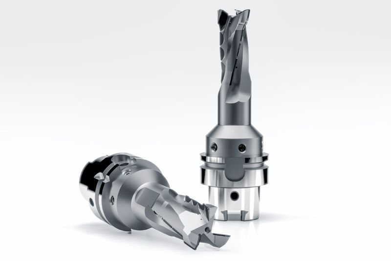
OptiMill-Diamond-SPM
- Fresa PCD
- Operações de fresagem circular de vários diâmetros e superfícies
- Redução das trocas de ferramentas graças à utilização flexível da ferramenta
-
9 / 9
OptiMill-Alu-HPC-Pocket
- Fresa de esquadrejamento
- Fresamento de cavidade de materiais de alumínio
- Remoção ideal de cavacos
- Estabilidade otimizada


-
1 / 5
Fresa PCD para requisitos especiais de usinagem
-
2 / 5
Fresa de PCD com lâminas alternadamente dispostas
- Forças de corte reduzidas sobre toda a profundidade de usinagem
-
3 / 5
Fresa de PCD em espiral
- Acabamento de estruturas de paredes finas
-
4 / 5
Fresa helicoidal de PCD
- Recortar com maior profundidade de corte
-
5 / 5
Fresa de faceamento de PCD
- Faceamento com profundidades de corte até 10 mm
- Geração de perfis de superfície definidos para superfícies vedantes e de apoio


Case studies from the energy supply sector
-
03.11.2022
Efficient deburring with robots
The FlyCutter from MAPAL is ideally suited for deburring battery trays. Robot manufacturer KADIA is enthusiastic about the PCD-tipped milling tool.
-
11.05.2023
A strategy for battery frames
MAPAL’s electric mobility experts have designed a generic component that encompasses the main machining operations of a battery frame.
-
12.07.2023
Milling instead of drilling
Why milling instead of drilling can be a sensible alternative? MAPAL shows how higher process reliability and shorter machining times can be achieved.