01.01.2018
Trockenbearbeitung von Schichtverbundwerkstoffen im Flugzeugbau
MAPAL entwickelt Bohr-Senk-Werkzeuge für die gängigen Kombinationen
Die Herausforderungen, die Werkzeughersteller für optimale Lösungen in der Endmontage von Flugzeugen zu meistern haben, sind vielfältig. Dabei spielen nicht nur die unterschiedlichen Werkstoffe oder die Forderung nach höchster Prozesssicherheit, sondern auch das Kühlkonzept, die engen Toleranzvorgaben und die eingesetzten Maschinen eine entscheidende Rolle. MAPAL hat sich intensiv mit diesen Herausforderungen beschäftigt und entsprechende Werkzeugkonzepte auf den Markt gebracht. Unter anderem zur prozesssicheren Trockenbearbeitung von Materialkombinationen wie CFK-Aluminium oder verschiedenen Aluminiumlegierungen.

Hochfeste und gleichzeitig leichte Materialien sind in der Luftfahrt von zentraler Bedeutung. Durch neue Materialkombinationen können Flugzeugbauer das Gewicht senken, die Festigkeit und Korrosionsbeständigkeit erhöhen sowie eine Vereinfachung der Montage durch integrative Bauweise erreichen. Während Strukturbauteile aus Aluminium, Titan oder hochfesten Stählen auf Bearbeitungszentren oder Portalmaschinen bearbeitet werden, bearbeiten die Mitarbeiter in der Endmontage die Bauteile meist mit handgeführten Maschinen, Bohrvorschubeinheiten oder mithilfe von Robotern.
Deshalb unterscheiden sich die Anforderungen an die Werkzeughersteller und Werkzeuge für die Endmontage maßgeblich von denen für die Teilefertigung. Die bearbeiteten Bauteile in der Teilefertigung haben einen Wert von rund 1.000 bis 50.000 Euro haben. Die Bauteile in der Endmontage sind, abhängig vom Montagefortschritt, mit einem Wert von etwa 50.000 bis 2.000.000 Euro schon deutlich kostenintensiver. Die Flugzeugbauer müssen fehlerhafte Bearbeitungen entweder aufwendig und kostspielig manuell nacharbeiten oder die Bauteile komplett ersetzen. Aus diesem Grund wählen sie ihre Lieferanten für die Endmontage sehr gewissenhaft aus.
Welchen Herausforderungen begegnen Werkzeughersteller in der Endmontage?
Wie ist der Stand der Technik bei Bohrungen für Nietverbindungen?
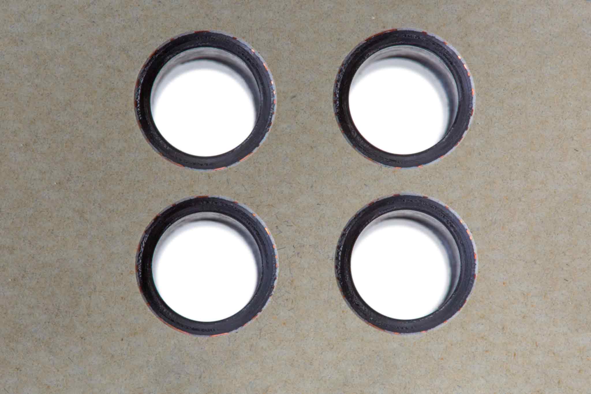
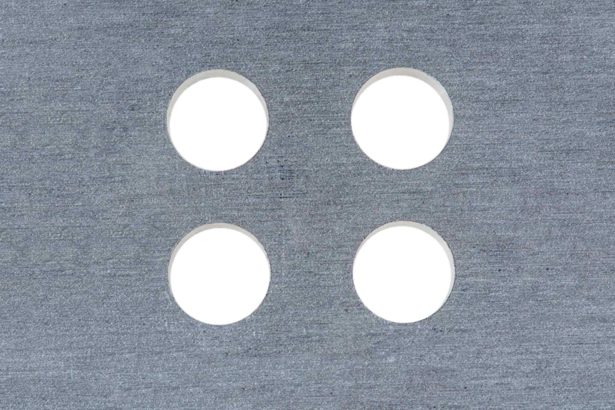
Flugzeughersteller nutzen für die Verbindung der Außenhaut mit den darunterliegenden Strukturbauteilen Nietverbindungen. Hierzu bringen die Mitarbeiter in der Endmontage unzählige Bohrungen ein. Um einen möglichst geringen Widerstand gegen Strömung zu erhalten (niedriger cW-Wert), werden die Nietköpfe in der Außenhaut versenkt. Deshalb ist am Bohrungseintritt eine zusätzliche Senkung erforderlich. In der Vergangenheit haben Flugzeugbauer dafür oft ein Prozess mit bis zu vier Einzelbearbeitungen eingesetzt - Vollbohren, Aufbohren, Reiben, Senken. Heute ist nur noch ein Schritt nötig - Bohrung und Senkung erledigen die entsprechenden Werkzeuge in nur einem Arbeitsschritt. Dadurch können auch Roboter diese Aufgabe automatisiert übernehmen.
Bisher nutzten die Flugzeughersteller für diese Bearbeitung in der Regel die Minimalmengenschmierung (MMS). Allerdings mussten die Mitarbeiter die Bauteile nach der Bearbeitung demontieren, reinigen und erneut montieren. Zudem gelangte der Schmierstoff in den Innenraum des Flugzeugs, wo Mitarbeiter parallel weitere Montageschritte durchführten. Die Forderung nach Werkzeugen zur Trockenbearbeitung verschiedener Schichtverbundwerkstoffe war die Konsequenz.
Welche Besonderheiten weist die Trockenbearbeitung auf?
Die Trockenbearbeitung läuft vollständig ohne den Einsatz eines Kühlschmierstoffs ab. Kühlschmierstoffe dienen in erster Linie dazu, die Wärme abzuführen und die Reibung zwischen Werkzeug und Werkstück zu reduzieren. Zudem unterstützen sie den Abtransport der Späne. Wird auf Kühlschmierstoff verzichtet, müssen die Werkzeuge diese Aufgaben übernehmen. Daraus ergeben sich die zentralen Herausforderungen an die Werkzeuge, wenn die Flugzeugbauer ihren Bohrprozess auf die Trockenbearbeitung umstellen:
- Wärme abführen
- Wärmeentwicklung vermeiden
- Späne abtransportieren
Wird die Wärme nicht rechtzeitig abgeführt, steit die Temperatur auf einen zu hohen Wert und das Material wird beschädigt. So führt beispielweise ein zu hoher Wärmeeintrag bei faserverstärktem Kohlenstoff dazu, dass das verwendete Harz verbrennt. Dadurch wird das Material spröde. Bei Aluminium bildet sich ein höherer Grat.
Worauf liegt der Fokus bei Bearbeitungen in einem Schritt?
Im Gegensatz zu einem mehrstufigen Bohrprozess muss das Kombinationswerkzeug beim Bearbeiten alle Arbeitsschritte (Vollbohren, Aufbohren, Reiben und Senken) übernehmen. Es fertigt die Bohrung für die Nietverbindung in einem Schritt. Damit ist zum einen die Position der Bohrung und zum anderen die Flucht zwischen dem zylindrischen Teil der Bohrung und der Senkung gewährleistet. Ein Winkelfehler oder Versatz wie bei mehrstufigen Operationen ist ausgeschlossen.
Qualitätsmerkmale der Bohrung:
- Durchmesser
- Übergangsradius
- Senkwinkel
Neben diesen Qualitätsmerkmalen spielt der Austrittsgrat eine große Rolle. Sollte sich bei einer mehrstufigen, manuellen Bohrbearbeitung, am Bohrungsaustritt ein Grat gebildet haben, so kann der Mitarbeiter diesen ohne großen Aufwand mit Hilfe eines Kegelsenkers entfernen. Läuft der Prozess allerdings automatisiert in nur einem Schritt ab, ist ein manuelles Entgraten nicht möglich. Daher muss das entsprechende Werkzeug in der Lage sein, nahezu gratfrei zu bohren. Die Flugzeugbauer geben hier in der Regel eine maximale Grathöhe von 0,1 mm vor. Zum Grat am Bohrungsaustritt kommt der interlaminare Grat zwischen den Lagen. Bildet sich dieser, müssen die Mitarbeiter des Flugzeugbauers den Schichtverbund am Ende der Bohroperationen demontieren, um den interlaminaren Grat zu entfernen. Diese Demontage ist zeitaufwendig und kostenintensiv, daher darf auch dieser Grat erst gar nicht entstehen.
Wie wirkt sich das Maschinenkonzept auf die Zerspanung aus?
Das Maschinenkonzept beeinflusst maßgeblich die Werkzeuggeometrie. CNC-Anwendungen auf Bearbeitungszentren oder Portalmaschinen zeichnen sich durch hohe Steifigkeit und stabile Maschinenführung aus. Das Werkzeug wird dadurch sehr gut in der Bohrung geführt. Anwendungen mit Bohrvorschubeinheiten, Robotern oder Handbohrmaschinen sind weniger stabil und erfordern für hohe Genauigkeiten und damit Werkzeuge mit zusätzlichen Stabilisierungsmerkmalen.
Eine weitere Besonderheit beim Einsatz von Bohrvorschubeinheiten sind die sogenannten „Nosepieces“, auch Führungsbuchsen genannt. Durch eine lange schmale Führungsbuchse transportiert das System die Späne über das Werkzeug ab. Das Ziel der Späne ist ein Absaugkanal am Ende der Führungsbuchse. Damit dieser Prozess funktioniert, sind lange Spanräume notwendig. Der Werkzeughersteller muss diese richtig dimensionieren und an die jeweilige Bearbeitung anpassen.
Für die Bohrungen an der Außenhaut (Rumpf und Flügel) setzen Flugzeugbauer meist Portalmaschinen oder Roboter ein. Die unzugänglichen Bohrbearbeitungen, hauptsächlich in der Endmontage realisieren die Mitarbeiter dann mit Bohrvorschubeinheiten oder mit Handbohrmaschinen gebohrt.
Welche Herausforderungen bestimmen die Bearbeitung von Schichtverbundwerkstoffen?
Was ist bei Werkzeugen für die Bearbeitung von Schichtverbundwerkstoffen zu beachten?
Bei der Paarung CFK-Titan werden Werkzeuge benötigt, deren Schneidkante stabil genug ist, um dem duktilen Titan zu widerstehen. Gleichzeitig muss die Schneide scharf sein, um das CFK zu schneiden. Ob ein Bohrprozess allein ausreicht, um die Bohrung zu fertigen, oder ob die Bohrung im Nachgang noch gerieben werden muss, hängt bei dieser Materialkombination von der geforderten Bohrungstoleranz ab.
Werkzeuge zum Bohren von Schichtverbundwerkstoffen aus unterschiedlichen Aluminiumlegierungen, beispielsweise 7050 und 2024, benötigen keine verschleißhemmende Beschichtung. Denn die im Flugzeugbau verwendeten Aluminiumsorten enthalten wenig bis kein Silizium und können somit nahezu verschleißfrei gebohrt werden. Dies unterscheidet diesen Schichtverbund bei der Bearbeitung entscheidend von Verbunden, die CFK enthalten.
Werkzeuge, die für Materialkombinationen eingesetzt werden, die CFK enthalten, versehen die Werkzeughersteller beispielsweise generell mit einer Diamantschicht. Diese wirkt der Abrasion des CFK entgegen und ermöglicht hohe Standzeiten. Ein Nachschliff dieser Werkzeuge ist nicht möglich, da die verwendete Diamantschicht eine sehr hohe Härte aufweist.
Was müssen Werkzeughersteller bei der Auslegung berücksichtigen, um Prozesssicherheit bei der Bearbeitung zu gewährleisten?
- Qualitätsanforderung
- Material
- Bearbeitungsprozess
Da die Großzahl der Bohrungen im Flugzeug aufgrund der Nieten eine Senkung benötigen, ist der Bohrungsaustritt kritischer zu bewerten, um kostenintensive Nacharbeiten auszuschließen.
Was genau müssen die Werkzeuge verhindern?
- Delaminationen
- Faserüberstände
- Gratbildung
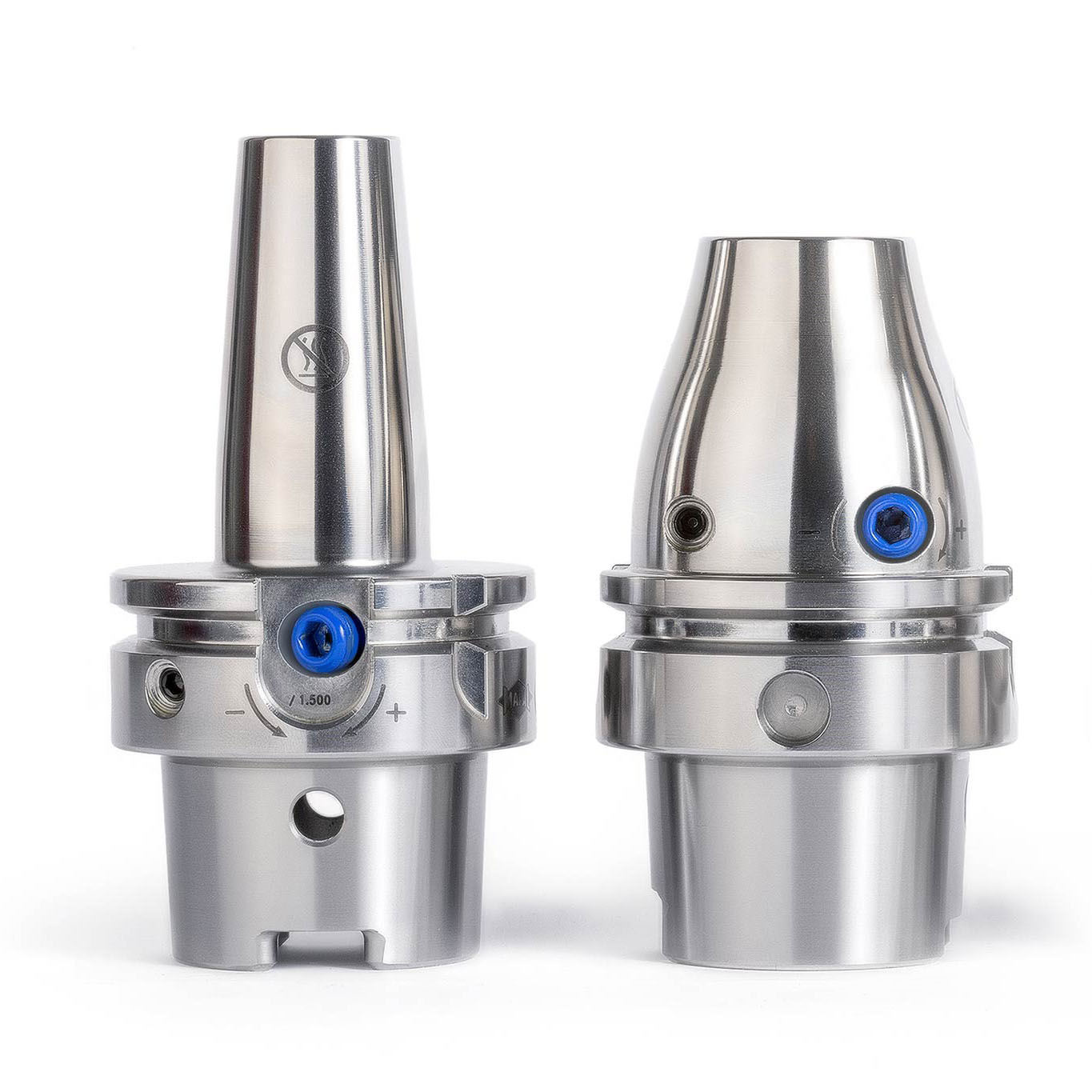
Wichtig ist bei der Bearbeitung aller Einzelmaterialien sowie aller Schichtverbundwerkstoffe zudem die Spanabfuhr. Ist diese nicht gewährleistet, liegt die Bohrungsqualität beim Trockenbohren schnell deutlich außerhalb der geforderten Toleranzen. Die größte Herausforderung bei der Entwicklung eines Trockenbohrers stellt aber die Anpassung der Werkzeuggeometrie auf das labile Bearbeitungssystem der Bohrvorschubeinheiten in Kombination mit Schnittparametern und Spannsystemen (ConcentricCollet) dar.
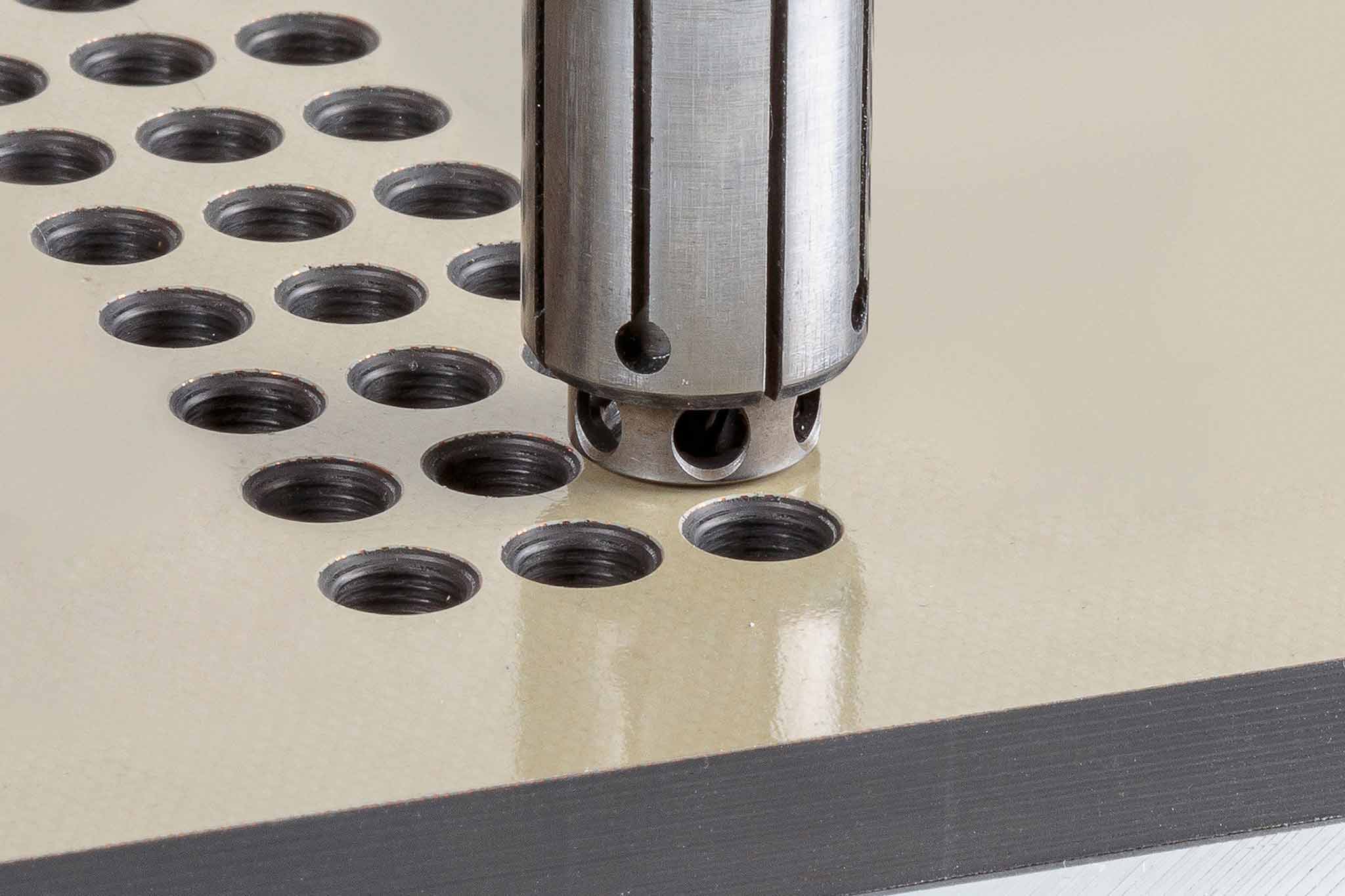
MAPAL Kombinationswerkzeug für die Trockenbearbeitung von Alu-Alu-Kombinationen

Im Einsatz bei einem Flugzeughersteller: das Bohr-Senk-Werkzeug zur Bearbeitung von Alu-Alu-Kombinationen
- Einsatzort: Längsnaht im hinteren Hauptfeld
- Durchmesser: 4,748 mm
- Senkstufe: 100°
- Drehzahl: 2.959 min-1
- Vorschub: 0,154 mm
- Standzeit: 1600 Bohrungen
- Toleranz: 4,73-4,805 mm
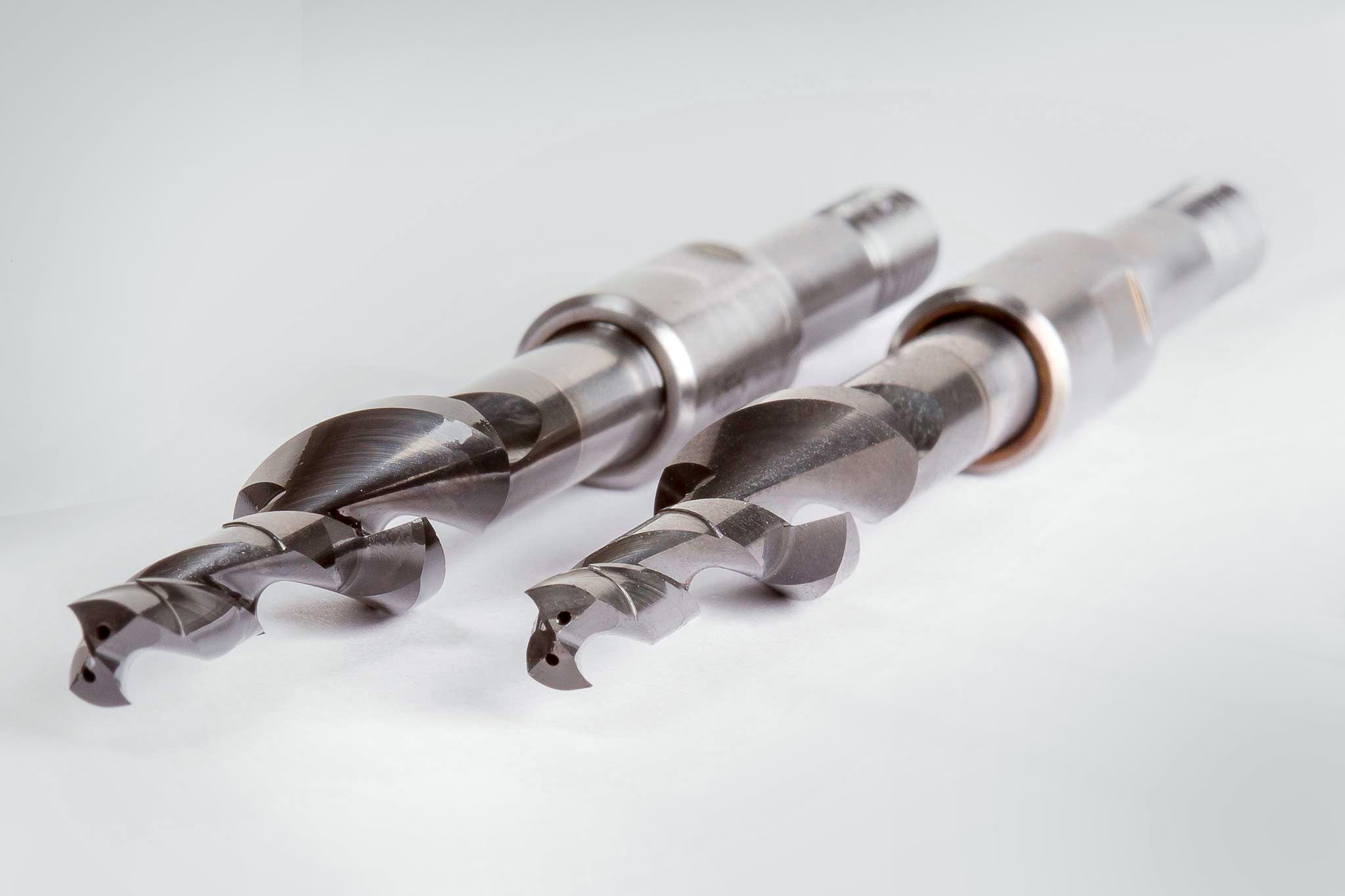
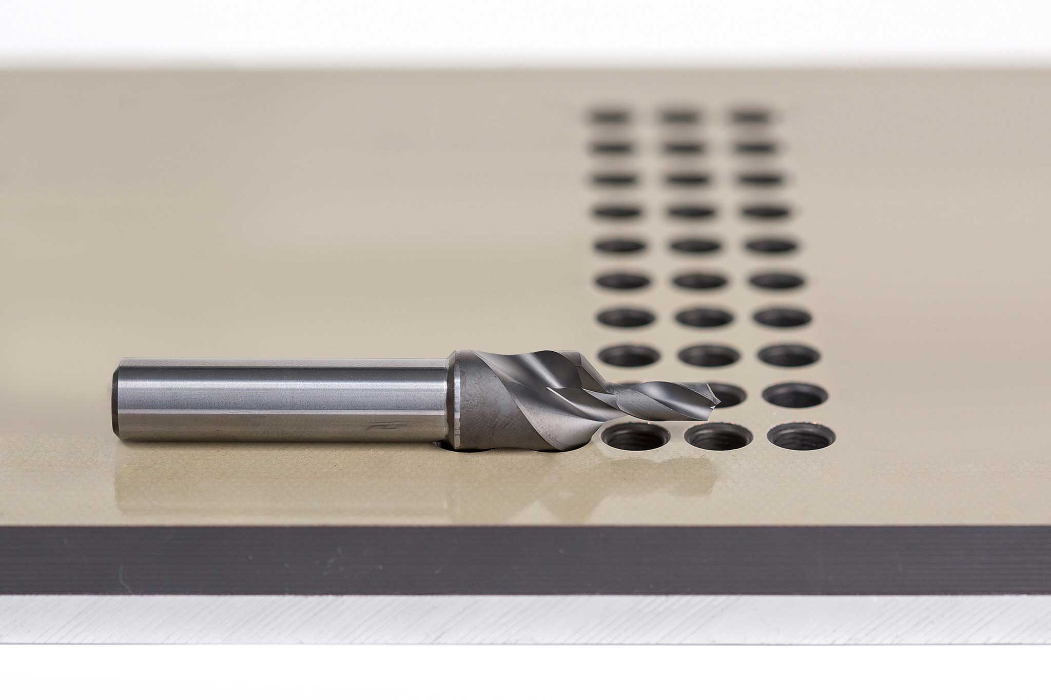
Bohr-Senk-Werkzeug zur Trockenbearbeitung von CFK-Alu-Kombinationen
Um Schichtverbundwerkstoffe aus CFK und Aluminium prozesssicher zu bearbeiten, hat MAPAL ebenfalls einen Bohrer mit Senkstufe zur Trockenbearbeitung entwickelt. Die spezielle Geometrie des Werkzeugs sorgt dafür, dass die entstehende Bearbeitungswärme nicht an das Bauteil abgegeben wird. Zudem werden weder das Bauteil noch die Arbeitsumgebung durch Kühlmittel verschmutzt. Der zweischneidige Bohrer aus Vollhartmetall vereint die Eigenschaften eines Bohrers zur Bearbeitung von Aluminium mit denen eines Bohrers zur CFK-Bearbeitung. Durch die speziell ausgeführten Spanräume ist die prozesssichere Abfuhr der Späne sichergestellt. Da CFK ein extrem abrasiver Werkstoff ist, ist der Bohrer diamantbeschichtet. Damit wird gegenüber einem unbeschichteten Bohrer die achtfache Standzeit erreicht.
Das Bohr-Senk-Werkzeug zur Trockenbearbeitung von CFK-Alu-Kombinationen ist erfolgreich bei Kunden im Einsatz. Es wird mit einer Drehzahl von 5.000 min-1 und einem Vorschub von 0,1 mm gearbeitet. Das Werkzeug überzeugt in der Praxis nicht nur durch die erreichten Ergebnisse hinsichtlich Prozesssicherheit, Standzeit und Bearbeitungsergebnis, sondern auch durch den ruhigen Bohrprozess.