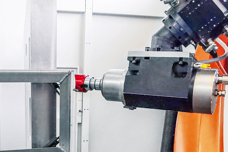
Carcasa para el suministro energético
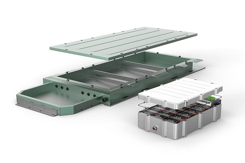
Se utilizan distintas carcasas para proteger los componentes electrónicos, como por ejemplo el sistema de batería o la electrónica de potencia, frente a influencias ambientales externas y para la fijación de componentes en el interior, a fin de garantizar su funcionamiento óptimo durante el accionamiento del vehículo. Los requisitos de la carcasa dependen del sistema electrónico y del concepto de propulsión. Actualmente, se utilizan diferentes materiales y procesos de fabricación.
CARACTERÍSTICAS
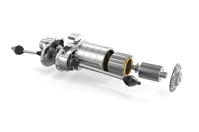
- Componentes inestables de paredes finas (propensos a vibraciones)
- Estructura de cubeta fundida o de bastidor con perfil hueco
- Parcialmente en aluminio con bajo contenido de silicio
- Grandes dimensiones (2 x 3 m)
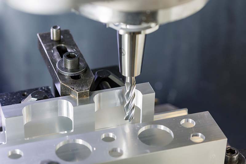
- Principalmente operaciones de taladrado y fresado, y roscas
- Requisitos de precisión y superficie para pasacables y conexiones de refrigeración


Resumen de herramientas
-
 1 / 9
1 / 9Programa estándar para el mecanizado de componentes estructurales de aluminio
- Geometría de cuchilla muy positiva
- Fuerzas de corte reducidas
- Corte con pocas vibraciones
-
2 / 9
OptiMill-SPM-Rough
- Desbaste de baja vibración con gran profundidad de corte
-
3 / 9
OptiMill-SPM
- Ideal para la fabricación de brechas o bolsillos
- Ejecución completa en metal duro o con cuchillas de PCD soldadas
-
4 / 9
OptiMill-SPM-Finish
- Acabado de grandes profundidades en una sola pasada
- Potente rendimiento con grandes enlazados
-
5 / 9
Tritan-Drill-Alu
- Fabricación de orificios lisos para roscar
- Tres insertos para velocidades de avance máximas
- Máxima precisión de posicionamiento mediante cuchilla transversal con autocentrado
-
6 / 9
MEGA-Drill-Alu
- Broca de metal duro (VHM)
- Taladrado con tiempos de ciclo reducidos
- Formación óptima de las virutas
- Procesos de taladrado eficaces con mayor número de diámetros iguales
-
7 / 9
FaceMill-Diamond-ES
- Fresa plana de PCD
- Desbaste y acabado de superficies frontales
- Mecanizado de superficies frontales con diferentes cotas a remover con una sola herramienta
- Posibilidad de operaciones de desbaste y acabado
-
8 / 9
OptiMill-Diamond-SPM
- Fresa PCD
- Operaciones de fresado circular de diversos diámetros y superficies
- Reducción de los cambios de herramienta gracias al uso flexible de la herramienta
-
9 / 9
OptiMill-Alu-HPC-Pocket
- Fresas de corte en esquina
- Fresado de cavidades en materiales de aluminio
- Eliminación óptima de las virutas
- Estabilidad óptima


-
1 / 5
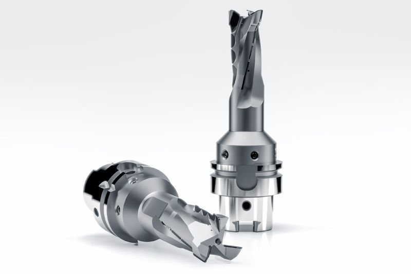
Fresa PCD para requisitos de mecanizado especiales
-
2 / 5
Fresa PCD con cuchillas dispuestas de forma alterna
- Bajas fuerzas de corte en toda la profundidad de mecanizado
-
3 / 5
Fresa PCD con forma espiral
- Acabado de estructuras de paredes finas
-
4 / 5
Fresas helicoidales de PCD
- Recorte con gran profundidad de corte
-
5 / 5
Fresa plana de PCD
- Fresado plano con profundidades de corte de hasta 10 mm
- Creación de perfiles superficiales definidos para superficies de contacto y apoyo


Case studies from the energy supply sector
-
03.11.2022
Efficient deburring with robots
The FlyCutter from MAPAL is ideally suited for deburring battery trays. Robot manufacturer KADIA is enthusiastic about the PCD-tipped milling tool.
-
11.05.2023
A strategy for battery frames
MAPAL’s electric mobility experts have designed a generic component that encompasses the main machining operations of a battery frame.
-
12.07.2023
Milling instead of drilling
Why milling instead of drilling can be a sensible alternative? MAPAL shows how higher process reliability and shorter machining times can be achieved.