03.11.2022
Efficient deburring with robots
KADIA system processes battery trays
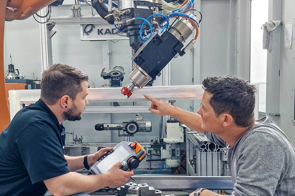
If a milling cutter is guided by a robot, the machining is fundamentally more unstable than on a machining centre. To reliably ensure the shortest cycle times in industrial production in this instance, KADIA is using MAPAL’s FlyCutter with three cutting edges in a newly developed system with three robots for deburring battery trays for electric vehicles.
The story of Nürtingen-based KADIA Produktion GmbH + Co began back in 1959 with the production of honing tools. The first honing machines were developed ten years later. The company tapped into another branch of business in 1981 with the manufacture of deburring machines. Today, KADIA is a leading specialist in honing and deburring technology and currently employs 200 people.
Its main customers are car manufacturers and suppliers, construction and agricultural machinery manufacturers, wind power plant producers and the aerospace industry. While the manufacturer offers standard machinery in different sizes for honing, in principle, custom machines are built for deburring. Customers include major machine manufacturers that bring KADIA on board as a deburring expert.
Pencil test for burrs
In mechanical machining, a distinction is made between loose and fixed burrs. After deburring, depending on what’s required, the part should have sharp edges, edge rounding or a chamfer, which is why this is also known as edge design. To assess a burr, KADIA uses a simple but meaningful test using the lead of a mechanical pencil extended by five millimetres. If it can be used to remove the burr, then the burr is loose. If the lead breaks, it’s a fixed burr, which needs to either be milled off or can be left in place, as it won’t come off later.
The size of the workpiece is also crucial to machining processes that make use of robots. Guiding the workpiece is favoured for smaller parts. The robot guides the workpiece along fixed processing units. In a tool-guided strategy, the robot arm processes a workpiece firmly clamped in place. “For bigger workpieces, I’m much more skilful with the milling cutter in hand than if I have to move the bulky part,” explains Jannik Weiss, Sales Specialist Deburring & Robotics at KADIA.
Zerspanung in der Versuchszelle
Kernstück der Entwicklung bei KADIA ist eine fünf mal sechs Meter große Versuchszelle mit einem Sechs-Achs-Industrieroboter und einer Schnellwechseleinheit. Hier kann der Prozess der späteren Anlage bereits getestet werden. Vorversuche ermitteln die optimalen Schnittdaten und prüfen die Stabilität. In der Zelle befinden sich 15 einwechselbare Einheiten, auf neun davon hat der Roboter einen automatisierten Zugriff mit einem Aktionsradius von 2,70 m. Eine Einheit stellt eine bestimmte Funktion dar, die für die Bearbeitung eines Bauteils gebraucht wird. Typischerweise besteht sie aus einer Motorspindel mit Schnittstelle und einem Zerspanungswerkzeug.
Ein Rundtisch als siebte Achse gehört ebenfalls zur Ausstattung der Versuchszelle, die zudem über genügend Freiraum verfügt, um weitere Anlagen, wie etwa eine Kühlmittelversorgung oder zusätzliche Prozesseinheiten unterbringen zu können. Oft sind bei KADIA gleich mehrere Teile für verschiedene Versuche in der Zelle gerüstet.
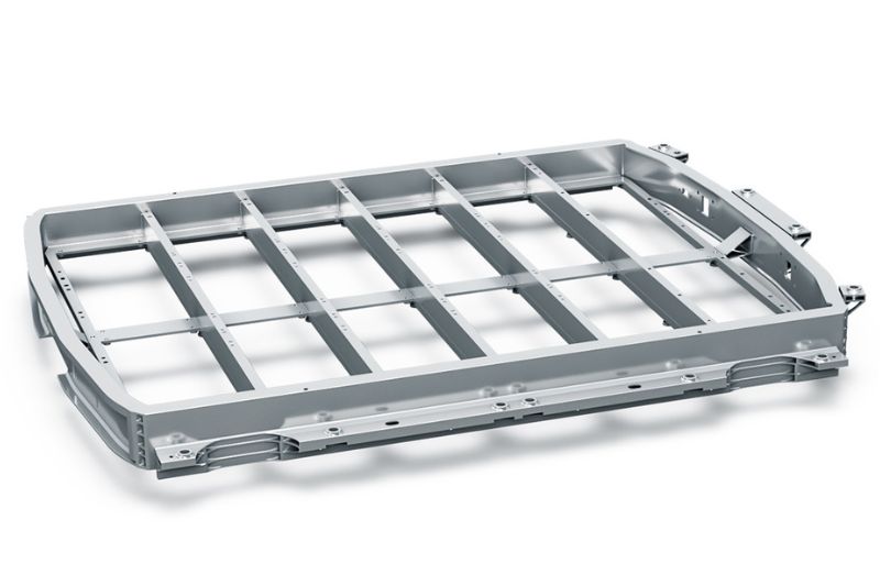
Für erste Vorversuche an einem Dummy-Bauteil der Batteriewanne verwendete KADIA einen bereits in der Fertigung vorhandenen Rundplattenfräser. Das Werkzeug erwies sich als völlig ungeeignet für die Aufgabe. Die auftretenden Schwingungen waren so stark, dass sogar die Bearbeitungsspindel Schaden nahm. Selbst bei niedrigen Schnittwerten machte sich die Geräuschkulisse beim Fräsen noch im Nebengebäude störend bemerkbar.
Wegen eines geeigneten Fräsers für das Aluminiumgehäuse wurde MAPAL als Problemlöser gewählt. „Wir informieren uns im Vorfeld, bei welchem Werkzeughersteller wir das Potenzial für eine Zusammenarbeit sehen“, berichtet Jannik Weiss. Zwar fokussiert man sich bei KADIA zunächst auf Standardwerkzeuge, doch war es durchaus ein Pluspunkt für MAPAL, dass der Werkzeughersteller bei Bedarf Sonderwerkzeuge entwickelt.
Zwei Fräser zur Auswahl
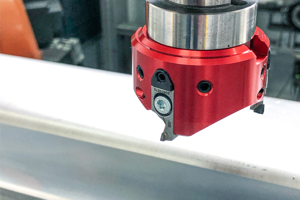
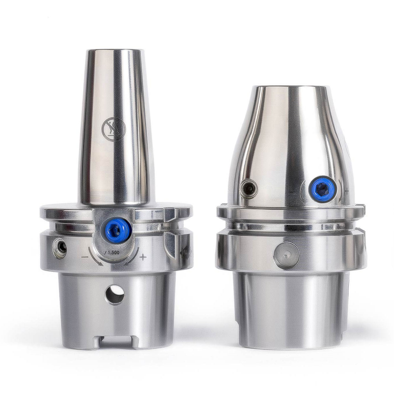
Norbert Meier wollte dem Kunden mit dem zweiten Fräser eine Alternative aufzeigen, hatte mit diesem Ergebnis aber gerechnet. „Unseren FlyCutter haben wir ganz speziell für derartige Anforderungen im Portfolio“, erläutert er. MAPAL hat das leichte Werkzeug gezielt für labile Voraussetzungen in der Bearbeitung entwickelt, wie sie bei Roboteranwendungen auftreten. Er ist optimiert für kleine Schnittstellen wie etwa BT30. Das innovative Design und der Einsatz von Aluminium sorgen für ein besonders geringes Gewicht des Fräskopfes. Mit dem bei KADIA verwendeten Durchmesser von 63 Millimetern wiegt der PKD-Fräskopf inklusive der Fräseinsätze gerade mal 220 Gramm.
Die feinfühlige Keiljustierung ermöglicht die μm-genaue Einstellung der Fräseinsätze. Die Schwalbenschwanzführung und eine zusätzliche Wurmschraube sorgen für einen perfekten Sitz und eine hohe Wiederholgenauigkeit bei der Montage der Fräseinsätze. Durch die spezielle, hochpositive Schneidengeometrie wirken nur geringe Kräfte auf das Bauteil und die vom Roboter geführte Werkzeugspindel.
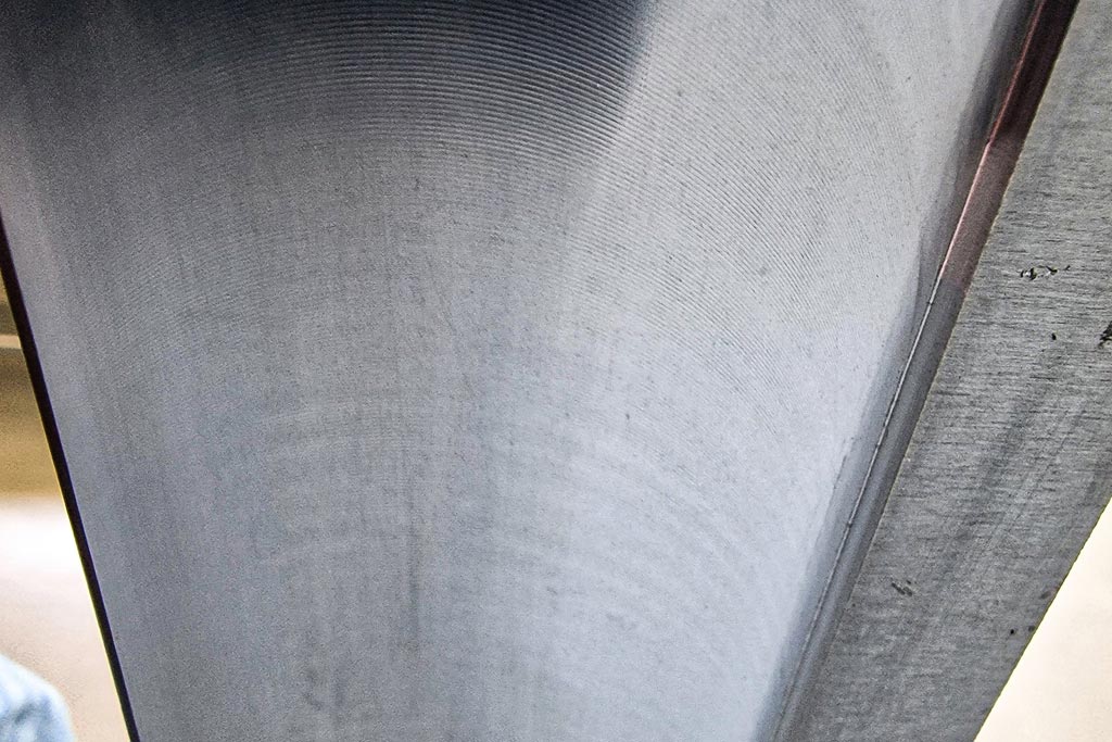
Bei der Bearbeitung der Batteriewanne kommt es auf Oberflächengenauigkeit im mµ-Bereich nicht an, im Gegenteil: Damit das vom Automobilhersteller aufzubringende Dichtmittel besser hält, war sogar eine gewisse Rauigkeit der Oberfläche gewünscht. Nur die Welligkeit durfte nicht zu groß werden. In den Versuchen wurde der Fräser über das Limit hinaus bewegt, um festzustellen, bis zu welchem Punkt entstehende Rattermarken an dem relativ dünnen Bauteil noch innerhalb der verlangten Toleranz liegen.
Schnittwerte und Positionierung sind wichtig
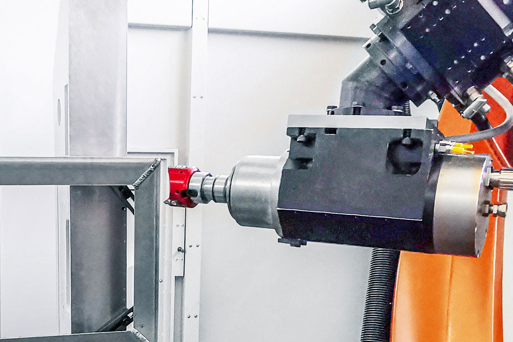
„Die Krux bei einer Roboterbearbeitung ist das Zusammenspiel zwischen Werkzeug, Vorrichtung und Roboter“, erläutert Norbert Meier. Die Steifigkeit ist ein grundsätzliches Problem bei der Bearbeitung. Je weiter der Roboterarm ausfährt, desto labiler wird die Zerspanung. In den Versuchen testet KADIA daher nicht nur unterschiedliche Schnittwerte, sondern auch verschiedene Positionierungen des Roboters vor oder neben dem Werkstück.
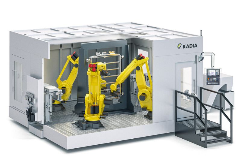
Für den vorliegenden Fall ermittelten die Partner als optimale Schnittdaten bei einer Spindeldrehzahl von 11.000 min-1 einen Vorschub von 0,16 m/s und eine Zustellung von 0,5 mm. Prozesssicher lieferte der FlyCutter eine sehr gute Oberflächenqualität. Diese Daten aus dem Versuchsstand hat KADIA in das Konzept für die Sondermaschine übernommen. Als wirtschaftlichste Lösung für die Serienfertigung hat der Hersteller dafür den Einsatz von drei Robotern in einer Zelle ermittelt. Während zwei sich die Bearbeitung der Vorderseite teilen, arbeitet der dritte an der Rückseite. Dem Kunden gibt KADIA nicht nur die Schnittdaten an die Hand, sondern kann bereits vor dem Bau der Maschine sagen, wie lange eine Bearbeitung dauert und was für eine Taktzeit damit zu realisieren ist. Das Entgraten einer großen Batteriewanne dauert demzufolge etwa 80 Sekunden. „Bei einem Roboterprozess sind solche Prozessangaben zu Schnittwerten noch nicht ganz so üblich wie bei einer CNC-Maschine. Je nach Positionierung des Roboters erzeugen gleiche Daten andere Ergebnisse“, sagt Jannik Weiss.
Aufgrund der durchweg positiven Ergebnisse wollen KADIA und MAPAL ihre Zusammenarbeit vertiefen. Weitere Versuche für unterschiedliche Bearbeitungsprozesse sind bereits in Planung.

Kontakt
Kathrin Rehor Public Relations Kathrin.Rehor@mapal.com Tel.: +49 7361 585 3342