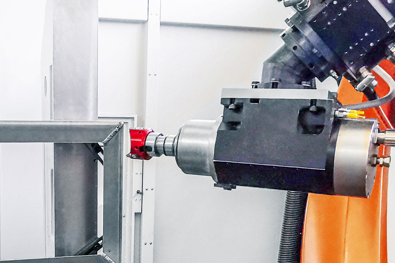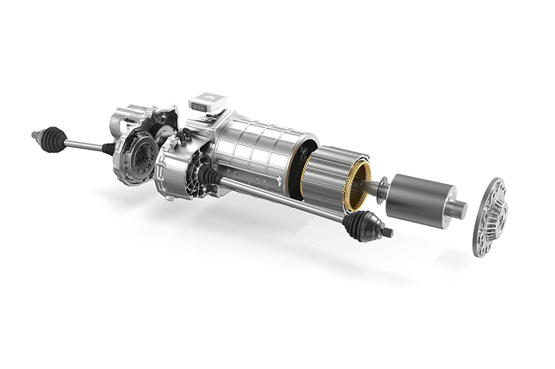
Boîtier pour l'alimentation électrique
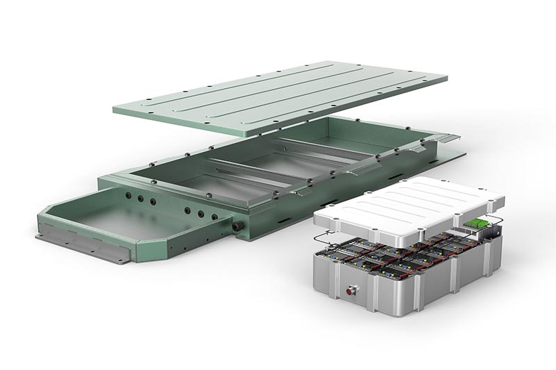
Divers boîtiers sont utilisés pour protéger les composants électroniques, tels que le système de batterie ou l'électronique de puissance, contre les influences extérieures de l'environnement et pour fixer les composants à l'intérieur afin d'assurer leur parfait fonctionnement pendant l'utilisation du véhicule. Les exigences relatives aux boîtiers dépendent du système électronique et du concept d'entraînement. Actuellement, différents matériaux et procédés de fabrication sont utilisés.
CARACTÉRISTIQUES
- Composants fragiles à parois minces (sensibles aux vibrations)
- Structure en cuve coulée ou construction à cadre en profilés creux
- Aluminium partiellement pauvre en silicium
- Grande surface (2 x 3 m)
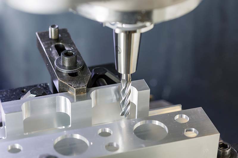
- Opérations de forage, de fraisage et de filetage, principalement
- Exigences de précision et de surface pour les passages de câble et les raccords de refroidissement


Aperçu de l'outil
-
 1 / 9
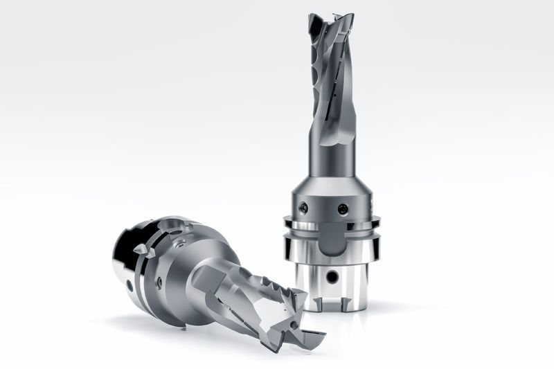
1 / 9Programme standard pour l'usinage de composants structurels en aluminium
- Géométrie de coupe très positive
- Réduction des forces de coupe
- Coupe à faible vibration
-
2 / 9
OptiMill-SPM-Rough
- Ébauche à faible vibration et grande profondeur de coupe
-
3 / 9
OptiMill-SPM
- Idéal pour la réalisation de percées ou de poches
- Conception en carbure monobloc ou PCD brasé
-
4 / 9
OptiMill-SPM-Finish
- Finition en profondeur en un seul passage
- D'excellentes performances à des contacts élevés
-
5 / 9
Tritan-Drill-Alu
- Fabrication de carottages
- Trois arêtes de coupe pour des vitesses d'avance maximales
- Précision de positionnement maximale grâce à une arête transversale autocentrée
-
6 / 9
MEGA-Drill-Alu
- Foret en carbure monobloc
- Perçage avec temps de cycle réduit
- Focus sur la formation de copeaux
- Processus de perçage efficaces avec un plus grand nombre de diamètres identiques
-
7 / 9
FaceMill-Diamond-ES
- Fraise à planer en PCD
- Ébauche et finition de surfaces planes
- Un seul outil pour usiner des surfaces planes à différentes épaisseurs d'enlèvement de matière
- Utilisation possible pour les opérations d'ébauche et de finition
-
8 / 9
OptiMill-Diamond-SPM
- Fraises PCD
- Opérations de fraisage circulaires de différents diamètres et surfaces
- Réduction des changements d'outils grâce à une utilisation flexible de l'outil
-
9 / 9
OptiMill-Alu-HPC-Pocket
- Fraises à dresser
- Fraisage de poches d'aluminium
- Évacuation optimale des copeaux
- Stabilité optimale


-
1 / 5
Fraise en PCD pour les exigences spéciales d'usinage
-
2 / 5
Fraise en PCD avec arêtes de coupe disposées en alternance
- Faibles forces de coupe sur toute la profondeur d'usinage
-
3 / 5
Fraise à spirales en PCD
- Finition des structures à paroi mince
-
4 / 5
Fraise hélicoïdale en PCD
- Détourage avec grande profondeur de coupe
-
5 / 5
Fraise à planer en PCD
- Surfaçage avec profondeurs de coupe allant jusqu'à 10 mm
- Génération de profils de surface définis pour les surfaces d'étanchéité et de contact


Case studies from the energy supply sector
-
03.11.2022
Efficient deburring with robots
The FlyCutter from MAPAL is ideally suited for deburring battery trays. Robot manufacturer KADIA is enthusiastic about the PCD-tipped milling tool.
-
11.05.2023
A strategy for battery frames
MAPAL’s electric mobility experts have designed a generic component that encompasses the main machining operations of a battery frame.
-
12.07.2023
Milling instead of drilling
Why milling instead of drilling can be a sensible alternative? MAPAL shows how higher process reliability and shorter machining times can be achieved.