01.09.2018
Reliable Machining of Structural Parts Susceptible to Vibration
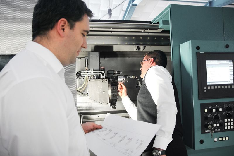
How customers machine demanding structural parts economically and reliably with a complete solution from MAPAL.
Thin-walled components can be found in a wide variety of industries. These components are often manufactured close to the final contour, but still require many machining tasks. The special challenge during machining is that these parts are very unstable and susceptible to vibrations due to their design. This entails special requirements for process and tool design.
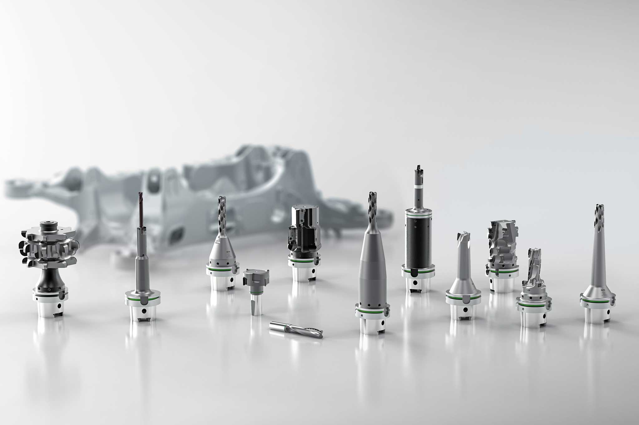
“It is important for our customers to machine these parts in one clamping set-up if possible”, emphasises Leander Bolz, Sales Manager of PCD tools at MAPAL. “In order to meet this requirement and to make all areas to be machined accessible for the tools as far as possible, reductions in the clamping set-up must be made. This means that the workpiece is not optimally supported and tends to vibrate”. Thin ribs, voids and interruptions to be machined as well as strongly fluctuating stock removal of the cast blank are also special conditions. In addition, a large number of tools are required for large parts with many machining operations. Leander Bolz: “Wherever possible, we therefore try to combine individual machining steps with combination tools. In this way, we reduce non-productive times and the number of tool stations required.”
MAPAL has a comprehensive understanding of the process with regard to the machining of unstable structural parts and is thus in a position to implement economical and reliable processes. Several starting points are of importance here. First of all, the cutting values can be finely adjusted so that rising vibrations can be avoided. Oscillations of the tool, which lead to vibrations and thus to poor tool lives and machining results, as well as oscillations of the workpiece must be avoided. The latter would cause the component to spring back against the cutting edge and could damage the tool. The second important aspect for fine tuning in the process design is the consideration of the basic tool body. Vibration is reduced by appropriate design and material selection. In addition, an intelligent arrangement of the cutting edges in shape and position keeps the cutting forces low. And finally, the machining process itself also offers possibilities for the reliable machining of vibration-prone components. Rethinking and choosing alternative sub-processes results in a changed distribution of forces that can increase process reliability. For example, the replacement of a solid drilling operation by a circular milling operation can stabilise the process.
Adapted tool designs make vibrations controllable
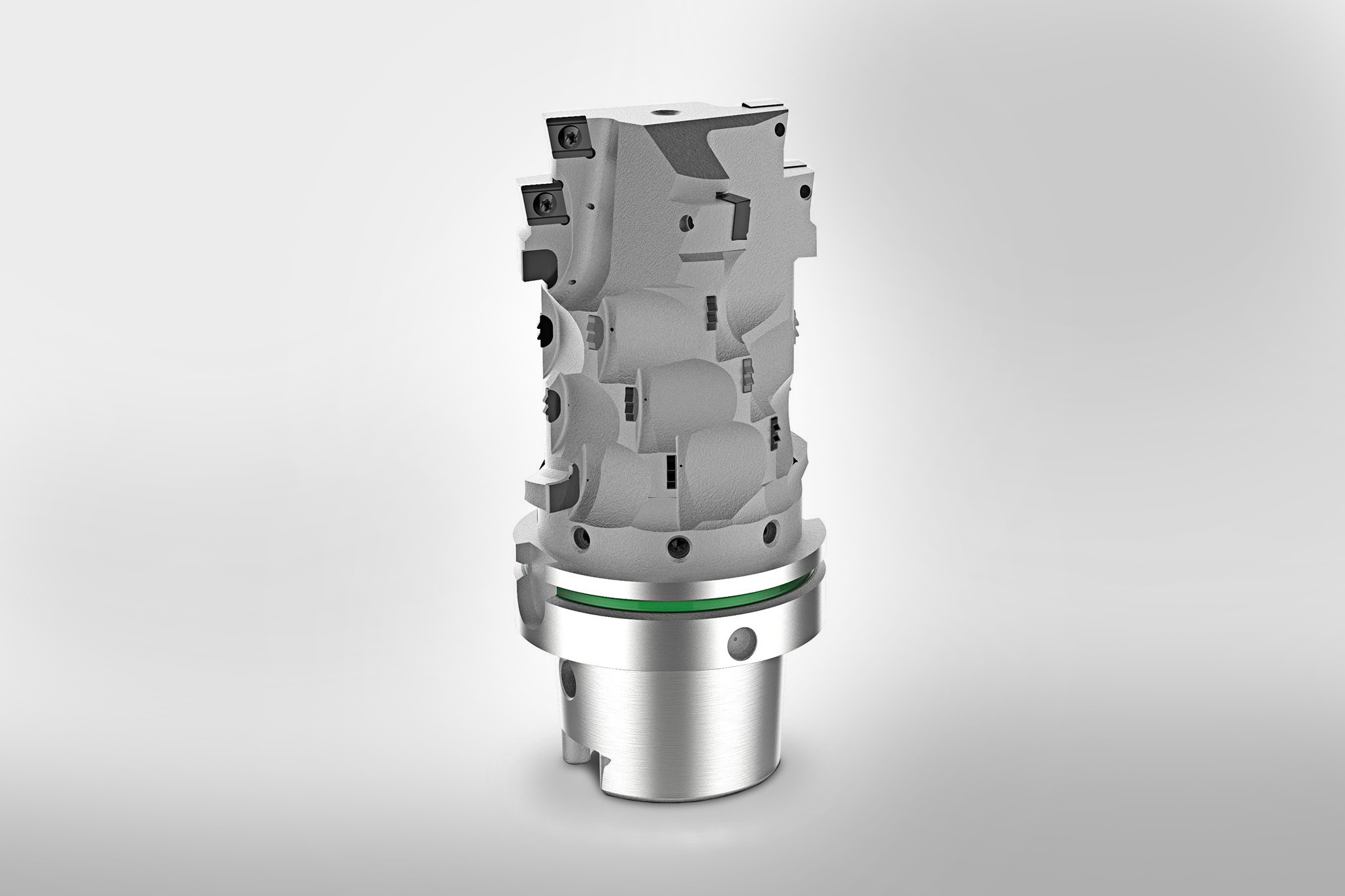
For example, we used a circular milling cutter for face and circumferential milling to machine a suspension part because we had to contend with strong vibrations,” says Leander Bolz, explaining an example of a successfully adapted tool for structural parts. For this purpose, a reduced helix angle and a reduced number of teeth were used for circumferential milling (Z=3). With the resulting reduced machining forces, the vibrations are controllable. The subsequent face milling step of the tool, which is particularly susceptible to wear, is consequently carried out with economical ISO indexable inserts. With a contact width of 6 mm and a cutting depth of 60 mm, maximum cutting values can be achieved. In addition, the tool has been given a face geometry with Z=6 in order to machine another face milling operation on the part economically and in the shortest cycle time.
Cutting data:
- vf = 2,700 mm/min
- fz = 0.1 mm
- n = 9,900 rpm
An adapted plunge milling cutter is also used in a suspension part. The tool semi-circularly plunges into a tab and cuts over the centre as the depth increases. An optimised face geometry and chip flute design, a load-reduced cutting edge arrangement as well as the integration of vibration dampers in the clamping tool used keep vibrations to a minimum and enable a reliable process.
Cutting data:
- vf = 1,200 mm/min
- fz = 0.1 mm
- n = 4,500 rpm
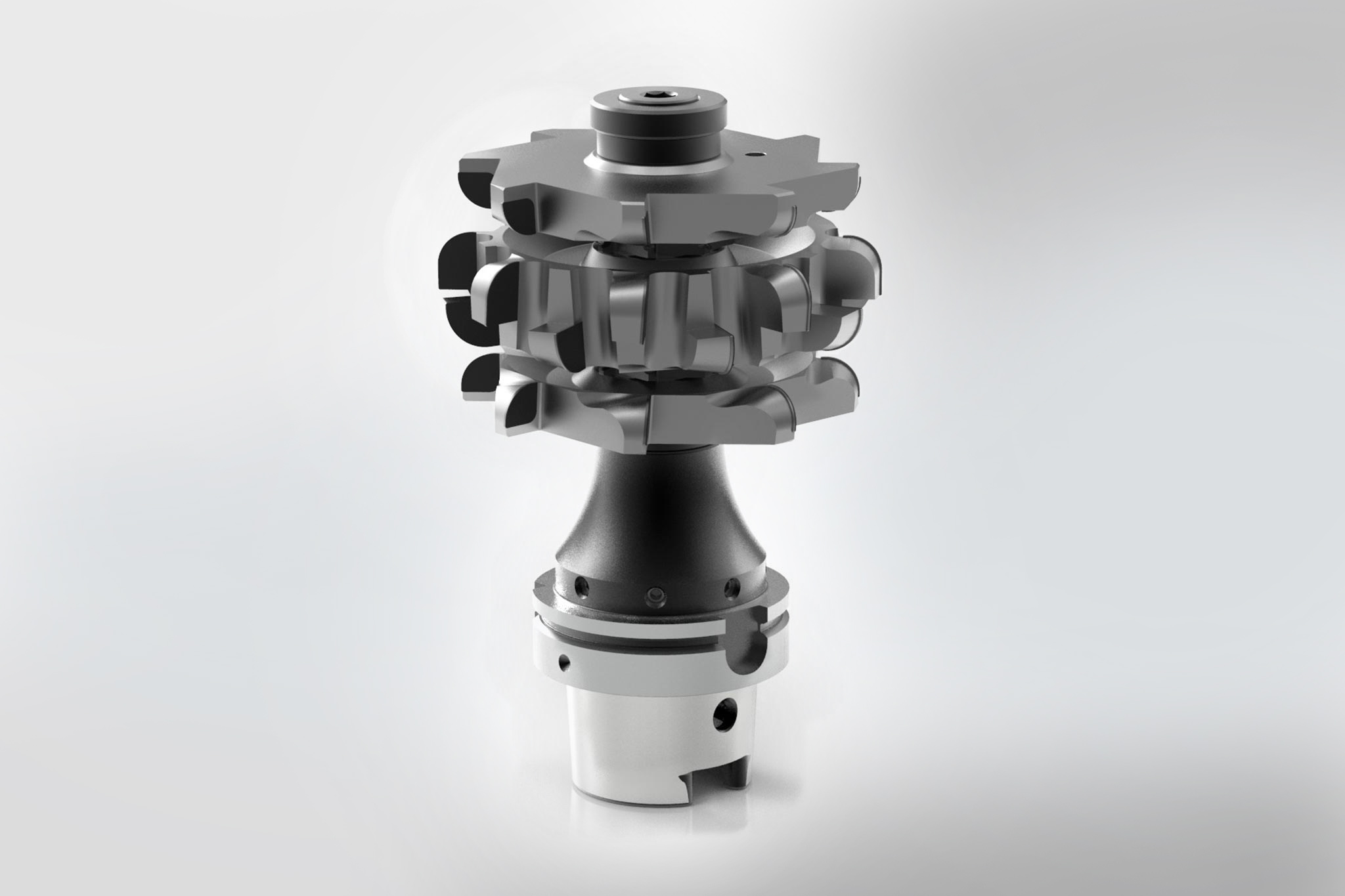
With a disc milling cutter set, several ribs and chambers are grooved simultaneously and the
face surfaces are finish machined. In order to keep the milling process quiet and to prevent the chips from jamming, the cutting action has been specially adapted and a cut distribution realised. The tool reliably machines all areas in one operation, which is of great importance due to the demand for a high number of cycles.
Cutting data:
- vf = 600 mm/min
- fz = 0.07 mm
- n = 1,500 rpm
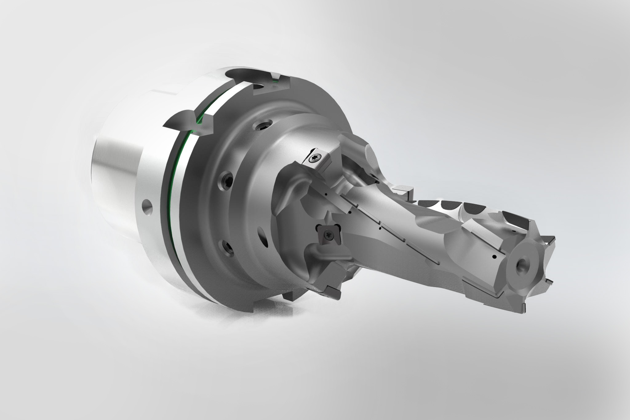
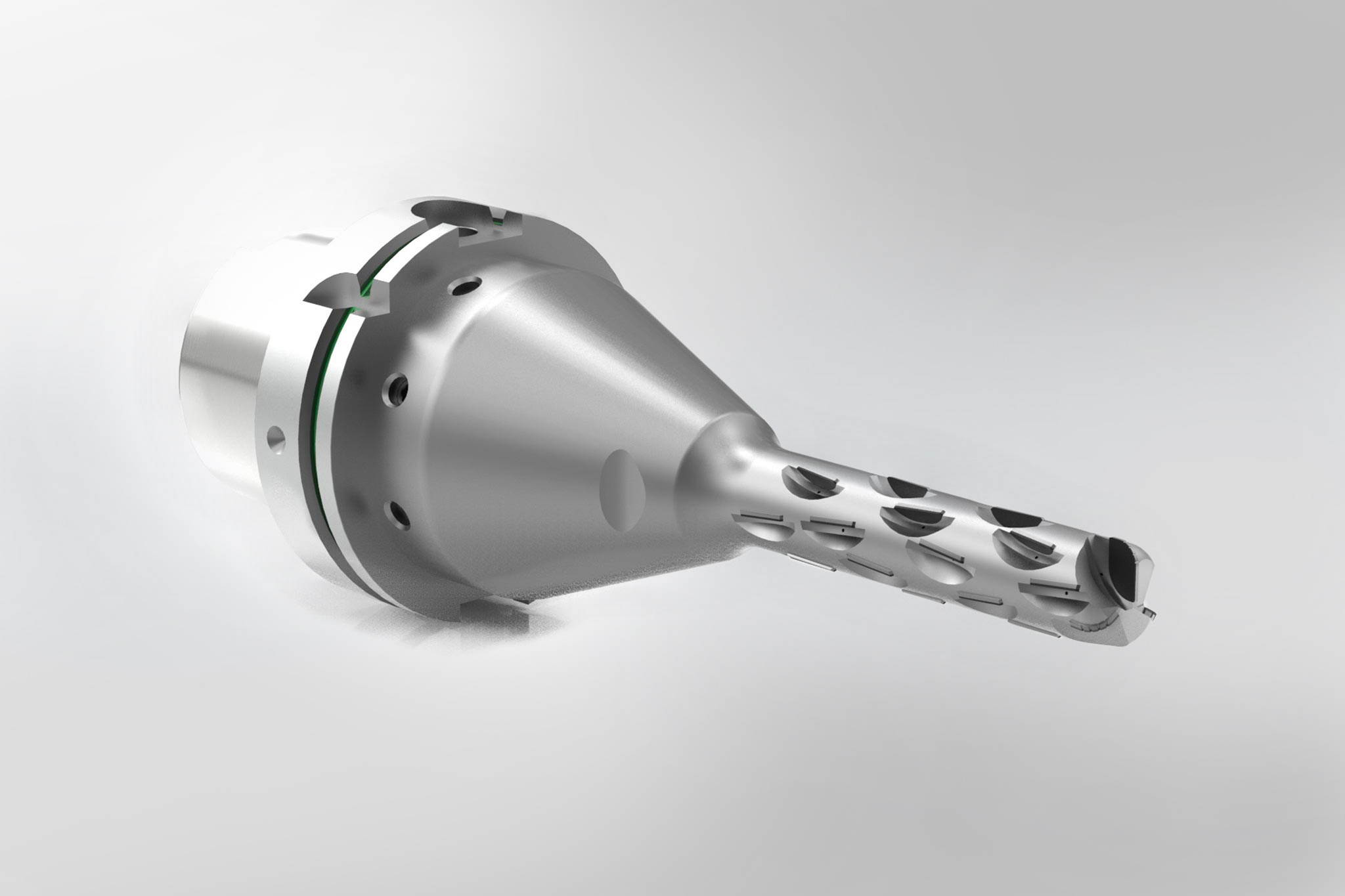
Bolz presents one particularly interesting tool used for the robot-assisted insertion of fixing
bores as a final example. “This is a combination tool in several respects,” he reports. “We have installed fixed brazed PCD cutting edges here for long tool lives and replaceable ISO indexable inserts for machining that is very susceptible to wear. In addition, the tool combines pre-machining and fine machining. And finally, it performs both a drilling and a milling operation.”
Milling cutting data:
- fz = 0.1 mm
- n = 3,800 rpm
Drilling cutting data:
- fz = 0.08 mm
- n = 480 rpm
MAPAL for a reliable process