03.11.2022
Wirtschaftliches Bearbeiten mit Robotern
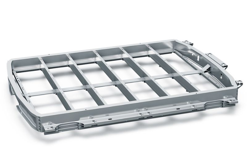
Anlage von KADIA bearbeitet Batteriewannen
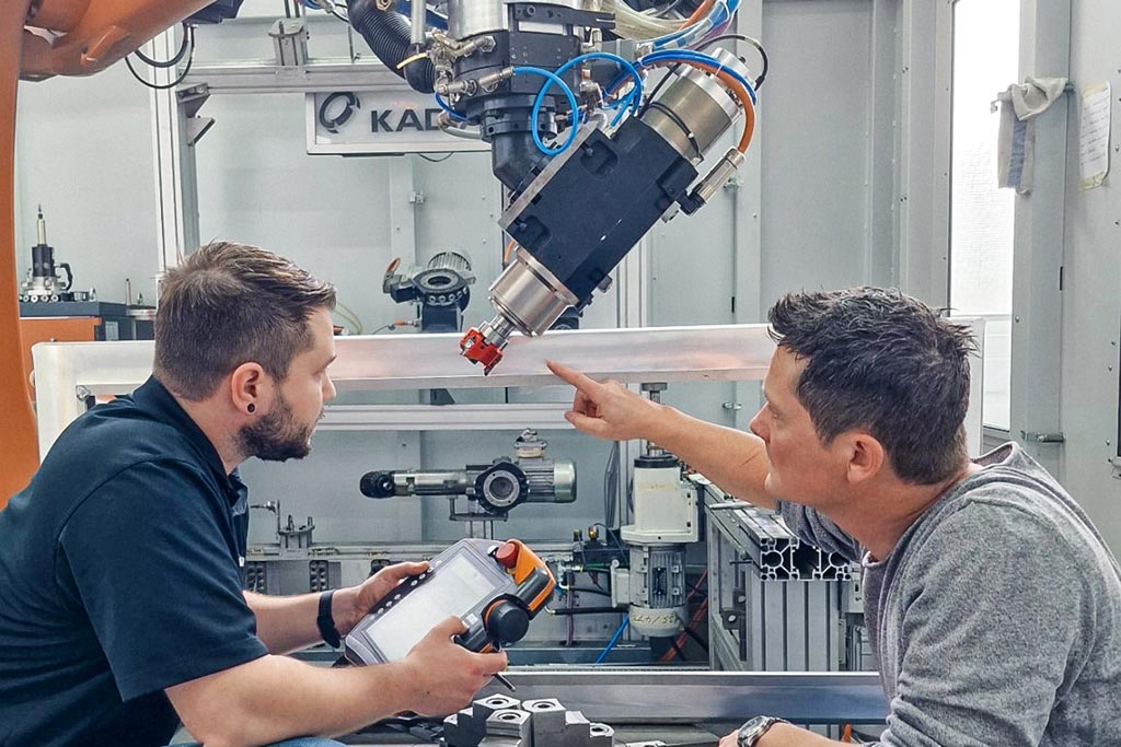
Wird ein Fräser von einem Roboter geführt, so ist die Bearbeitung grundsätzlich labiler als auf einem Bearbeitungszentrum. Um auch hier prozesssicher kürzeste Taktzeiten in der industriellen Produktion zu erreichen, setzt KADIA in einer neu entwickelten Anlage mit drei Robotern zum Entgraten von Batteriewannen für Elektrofahrzeuge den dreischneidigen FlyCutter von MAPAL ein.
Die Unternehmensgeschichte der KADIA Produktion GmbH + Co in Nürtingen begann 1959 mit der Herstellung von Honwerkzeugen. Zehn Jahre später wurden die ersten Honmaschinen entwickelt. Einen weiteren Geschäftszweig erschloss sich das Unternehmen seit 1981 mit der Herstellung von Entgratmaschinen. Heute gehört KADIA zu den führenden Spezialisten für Hon- und Entgrattechnologie und beschäftigt aktuell 200 Mitarbeiter.
Kunden sind vor allem Automobilhersteller und Zulieferer, Hersteller von Bau- und Agrarmaschinen oder Windkraftanlagen sowie der Flugzeugbau. Während der Hersteller für das Honen Standardmaschinen in verschiedenen Größen anbietet, werden für das Entgraten grundsätzlich Sondermaschinen gebaut. Zum Kundenkreis gehören auch große Maschinenhersteller, die KADIA als Entgratexperte mit an Bord holen.
Bleistifttest für Grate
Bei der mechanischen Bearbeitung unterscheidet man zwischen losen und festen Graten. Nach dem Entgraten soll das Bauteil je nach Anforderung scharfkantig, mit Kantenverrundung oder mit einer Fase ausgestattet sein, weshalb hier auch von Kantendesign gesprochen wird. Zur Beurteilung eines losen Grats setzt KADIA einen ebenso simplen wie aussagkräftigen Test ein, für den die um fünf Millimeter ausgefahrene Mine eines Druckbleistifts dient. Kann der Grat damit entfernt werden, ist er lose. Bricht die Mine ab, hat man es mit einem festen Grat zu tun, der je nach Anforderung weggefräst werden muss oder stehen bleiben darf, da er sich später nicht löst.
Für die Bearbeitung mit einem Roboter ist auch die Größe des Werkstücks entscheidend. Bei kleineren Bauteilen wird die Führung des Werkstücks favorisiert. Der Roboter fährt dabei das Werkstück an fest montierten Bearbeitungseinheiten entlang. Bei einer Werkzeug-geführten Strategie bearbeitet der Roboterarm ein fest eingespanntes Werkstück. „Bei großen Werkstücken bin ich mit dem Fräser in der Hand wesentlich geschickter, als wenn ich das sperrige Teil bewegen muss“, erläutert Jannik Weiss, Vertrieb Entgratmaschinen bei KADIA.
Zerspanung in der Versuchszelle
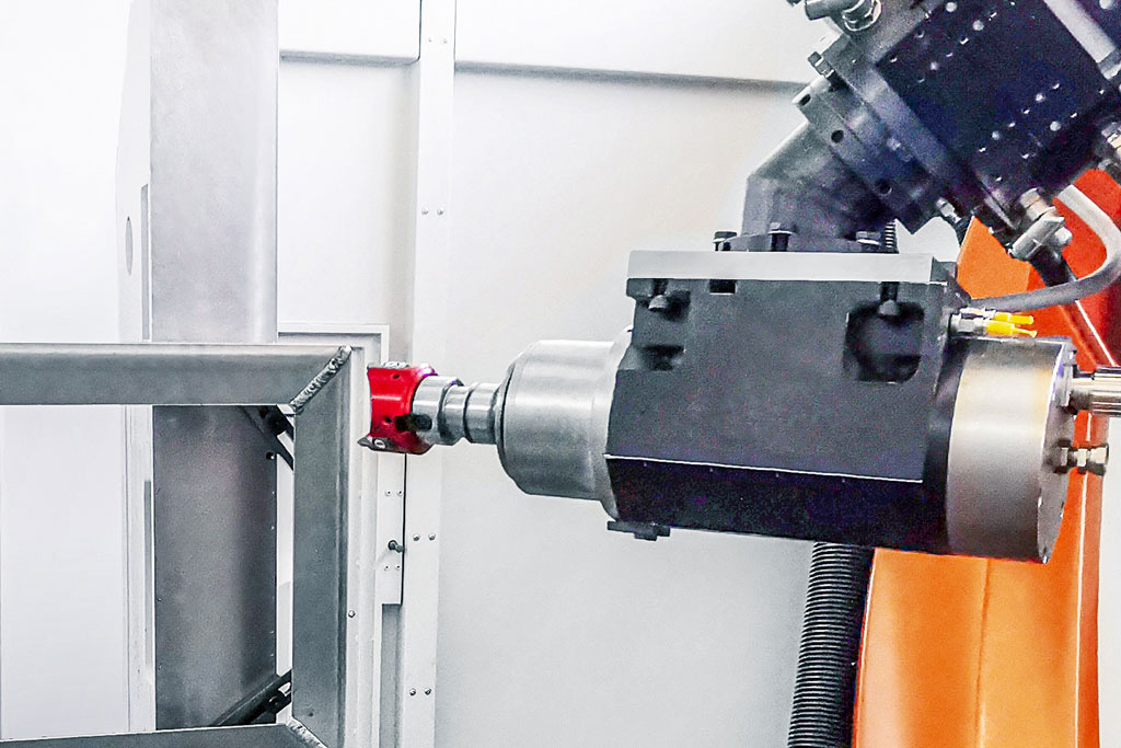
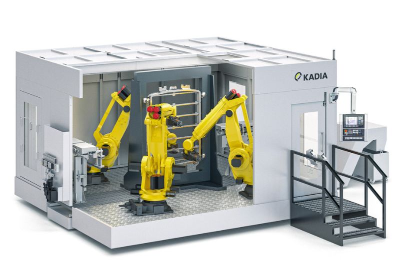
Kernstück der Entwicklung bei KADIA ist eine fünf mal sechs Meter große Versuchszelle mit einem Sechs-Achs-Industrieroboter und einer Schnellwechseleinheit. Hier kann der Prozess der späteren Anlage bereits getestet werden. Vorversuche ermitteln die optimalen Schnittdaten und prüfen die Stabilität. In der Zelle befinden sich 15 einwechselbare Einheiten, auf neun davon hat der Roboter einen automatisierten Zugriff mit einem Aktionsradius von 2,70 m. Eine Einheit stellt eine bestimmte Funktion dar, die für die Bearbeitung eines Bauteils gebraucht wird. Typischerweise besteht sie aus einer Motorspindel mit Schnittstelle und einem Zerspanungswerkzeug.
Ein Rundtisch als siebte Achse gehört ebenfalls zur Ausstattung der Versuchszelle, die zudem über genügend Freiraum verfügt, um weitere Anlagen, wie etwa eine Kühlmittelversorgung oder zusätzliche Prozesseinheiten unterbringen zu können. Oft sind bei KADIA gleich mehrere Teile für verschiedene Versuche in der Zelle gerüstet.
Für erste Vorversuche an einem Dummy-Bauteil der Batteriewanne verwendete KADIA einen bereits in der Fertigung vorhandenen Rundplattenfräser. Das Werkzeug erwies sich als völlig ungeeignet für die Aufgabe. Die auftretenden Schwingungen waren so stark, dass sogar die Bearbeitungsspindel Schaden nahm. Selbst bei niedrigen Schnittwerten machte sich die Geräuschkulisse beim Fräsen noch im Nebengebäude störend bemerkbar.
Wegen eines geeigneten Fräsers für das Aluminiumgehäuse wurde MAPAL als Problemlöser gewählt. „Wir informieren uns im Vorfeld, bei welchem Werkzeughersteller wir das Potenzial für eine Zusammenarbeit sehen“, berichtet Jannik Weiss. Zwar fokussiert man sich bei KADIA zunächst auf Standardwerkzeuge, doch war es durchaus ein Pluspunkt für MAPAL, dass der Werkzeughersteller bei Bedarf Sonderwerkzeuge entwickelt.
Zwei Fräser zur Auswahl
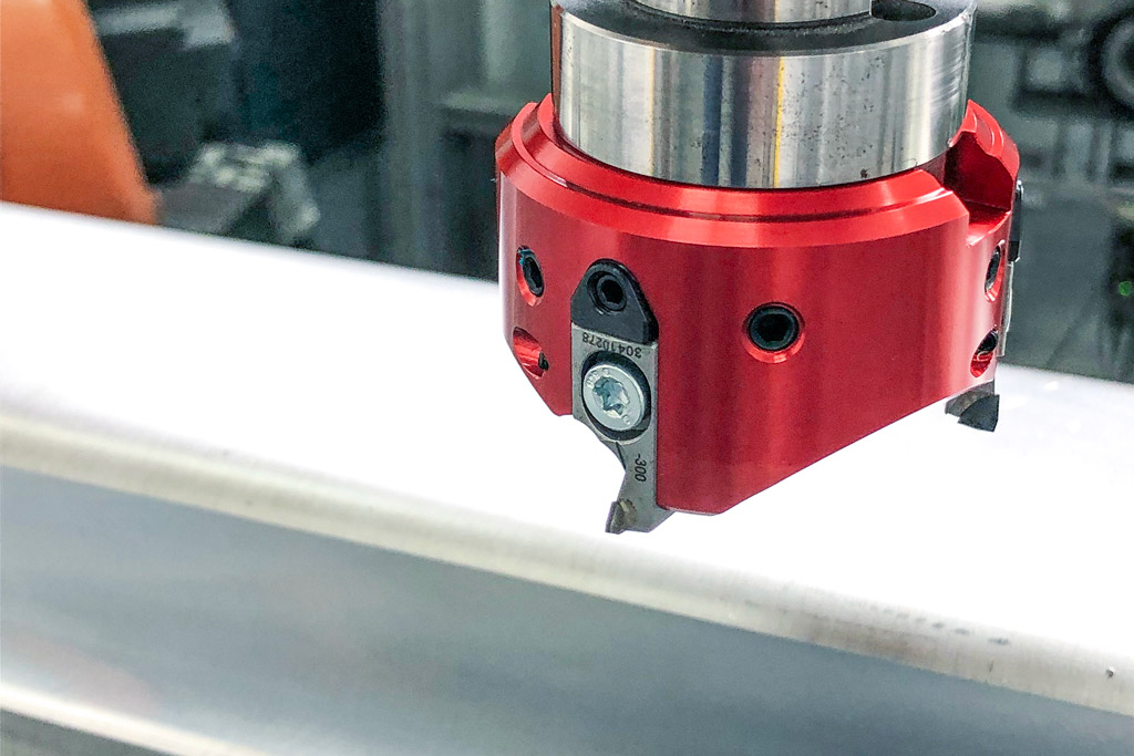
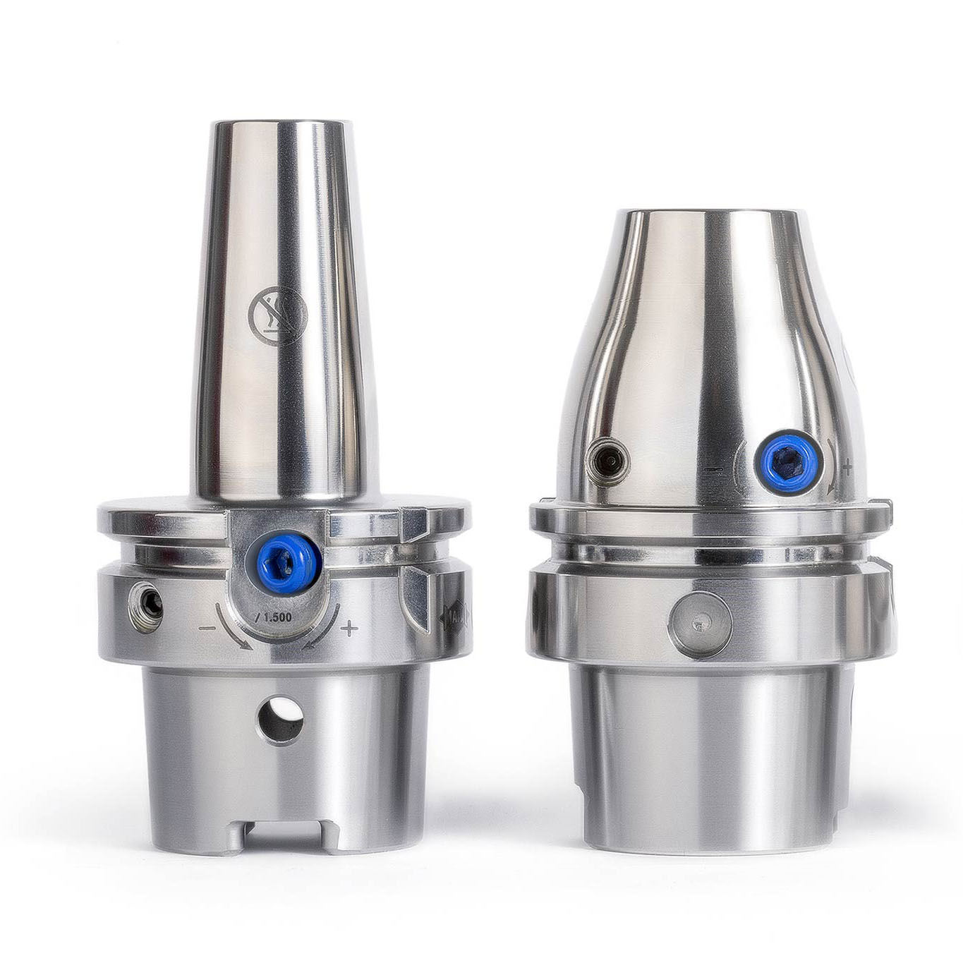
Norbert Meier wollte dem Kunden mit dem zweiten Fräser eine Alternative aufzeigen, hatte mit diesem Ergebnis aber gerechnet. „Unseren FlyCutter haben wir ganz speziell für derartige Anforderungen im Portfolio“, erläutert er. MAPAL hat das leichte Werkzeug gezielt für labile Voraussetzungen in der Bearbeitung entwickelt, wie sie bei Roboteranwendungen auftreten. Er ist optimiert für kleine Schnittstellen wie etwa BT30. Das innovative Design und der Einsatz von Aluminium sorgen für ein besonders geringes Gewicht des Fräskopfes. Mit dem bei KADIA verwendeten Durchmesser von 63 Millimetern wiegt der PKD-Fräskopf inklusive der Fräseinsätze gerade mal 220 Gramm.
Die feinfühlige Keiljustierung ermöglicht die μm-genaue Einstellung der Fräseinsätze. Die Schwalbenschwanzführung und eine zusätzliche Wurmschraube sorgen für einen perfekten Sitz und eine hohe Wiederholgenauigkeit bei der Montage der Fräseinsätze. Durch die spezielle, hochpositive Schneidengeometrie wirken nur geringe Kräfte auf das Bauteil und die vom Roboter geführte Werkzeugspindel.
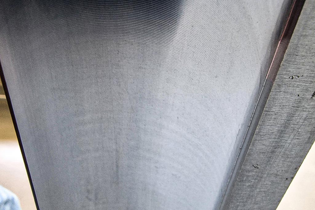
Bei der Bearbeitung der Batteriewanne kommt es auf Oberflächengenauigkeit im mµ-Bereich nicht an, im Gegenteil: Damit das vom Automobilhersteller aufzubringende Dichtmittel besser hält, war sogar eine gewisse Rauigkeit der Oberfläche gewünscht. Nur die Welligkeit durfte nicht zu groß werden. In den Versuchen wurde der Fräser über das Limit hinaus bewegt, um festzustellen, bis zu welchem Punkt entstehende Rattermarken an dem relativ dünnen Bauteil noch innerhalb der verlangten Toleranz liegen.
Schnittwerte und Positionierung sind wichtig
„Die Krux bei einer Roboterbearbeitung ist das Zusammenspiel zwischen Werkzeug, Vorrichtung und Roboter“, erläutert Norbert Meier. Die Steifigkeit ist ein grundsätzliches Problem bei der Bearbeitung. Je weiter der Roboterarm ausfährt, desto labiler wird die Zerspanung. In den Versuchen testet KADIA daher nicht nur unterschiedliche Schnittwerte, sondern auch verschiedene Positionierungen des Roboters vor oder neben dem Werkstück.
Für den vorliegenden Fall ermittelten die Partner als optimale Schnittdaten bei einer Spindeldrehzahl von 11.000 min-1 einen Vorschub von 0,16 m/s und eine Zustellung von 0,5 mm. Prozesssicher lieferte der FlyCutter eine sehr gute Oberflächenqualität. Diese Daten aus dem Versuchsstand hat KADIA in das Konzept für die Sondermaschine übernommen. Als wirtschaftlichste Lösung für die Serienfertigung hat der Hersteller dafür den Einsatz von drei Robotern in einer Zelle ermittelt. Während zwei sich die Bearbeitung der Vorderseite teilen, arbeitet der dritte an der Rückseite. Dem Kunden gibt KADIA nicht nur die Schnittdaten an die Hand, sondern kann bereits vor dem Bau der Maschine sagen, wie lange eine Bearbeitung dauert und was für eine Taktzeit damit zu realisieren ist. Das Entgraten einer großen Batteriewanne dauert demzufolge etwa 80 Sekunden. „Bei einem Roboterprozess sind solche Prozessangaben zu Schnittwerten noch nicht ganz so üblich wie bei einer CNC-Maschine. Je nach Positionierung des Roboters erzeugen gleiche Daten andere Ergebnisse“, sagt Jannik Weiss.
Aufgrund der durchweg positiven Ergebnisse wollen KADIA und MAPAL ihre Zusammenarbeit vertiefen. Weitere Versuche für unterschiedliche Bearbeitungsprozesse sind bereits in Planung.

Kontakt
Kathrin Rehor Public Relations Kathrin.Rehor@mapal.com Tel.: +49 7361 585 3342