01.05.2018
Using new solutions for a reliable process - relief bore is introduced in crancshafts
How an automobile manufacturer brings a new process safely into series production with MAPAL by its side as technology partner.
In cases where completely new machining processes are necessary for common components, innovative technology partners are needed to bring a new process safely into series production. In the course of downsizing, for example, a relief bore is introduced in crankshafts to reduce the weight. To reliably realise this bore through the different bearings in industrial-scale production, MAPAL has developed an appropriate tool concept that is already successfully in use.

To meet the requirements for smaller engines with increasing performance and reduced CO2 emissions, different adjusting screws are turned. In this way, new materials are developed that are lighter but more stable. Or the components of the engine are modified to reduce the rotating mass and in turn the fuel consumption. For example, crankshafts for different engines are
designed with a relief bore. This results in a significant weight reduction for the component.
designed with a relief bore. This results in a significant weight reduction for the component.
A new machining process
For the manufacturing of crankshafts, the relief bore entails an additional machining process. At Daimler AG, the process development, planning and tool management departments work closely together with the manufacturing department for this. However together with the internal parties, suppliers that provide the optimum tools are also needed for reliable machining.
When the process was first designed, tools from different suppliers were considered. To introduce the bore through the bearing of the crankshaft, several manufacturers developed concepts. The solution from MAPAL was convincing. Many employees of the precision tool manufacturer are permanently on site in production in Untertürkheim to fix problems and to
offer support during production. MAPAL has also done a lot of development work and performed trials during the entire time up to latest series. There is often a lack of time for this in mass production and so it is all the more worthwhile for manufacturing companies when a technology partner takes on this work.
offer support during production. MAPAL has also done a lot of development work and performed trials during the entire time up to latest series. There is often a lack of time for this in mass production and so it is all the more worthwhile for manufacturing companies when a technology partner takes on this work.
Four steps to a relief bore
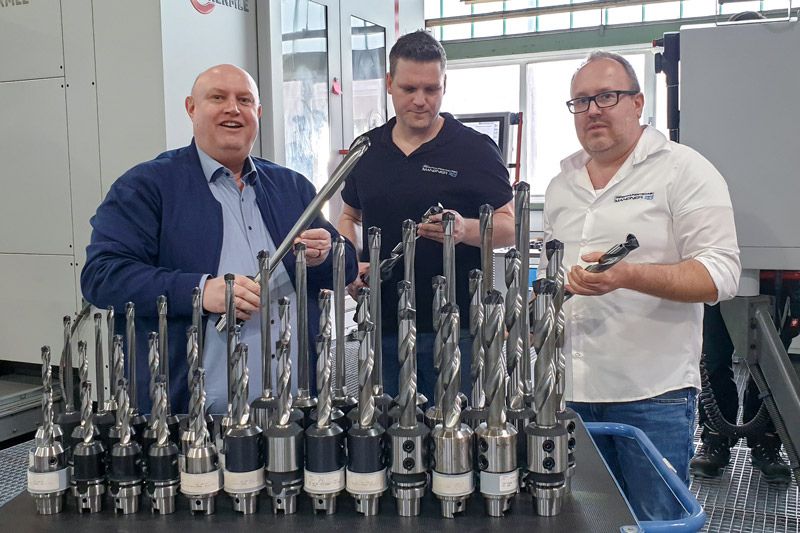
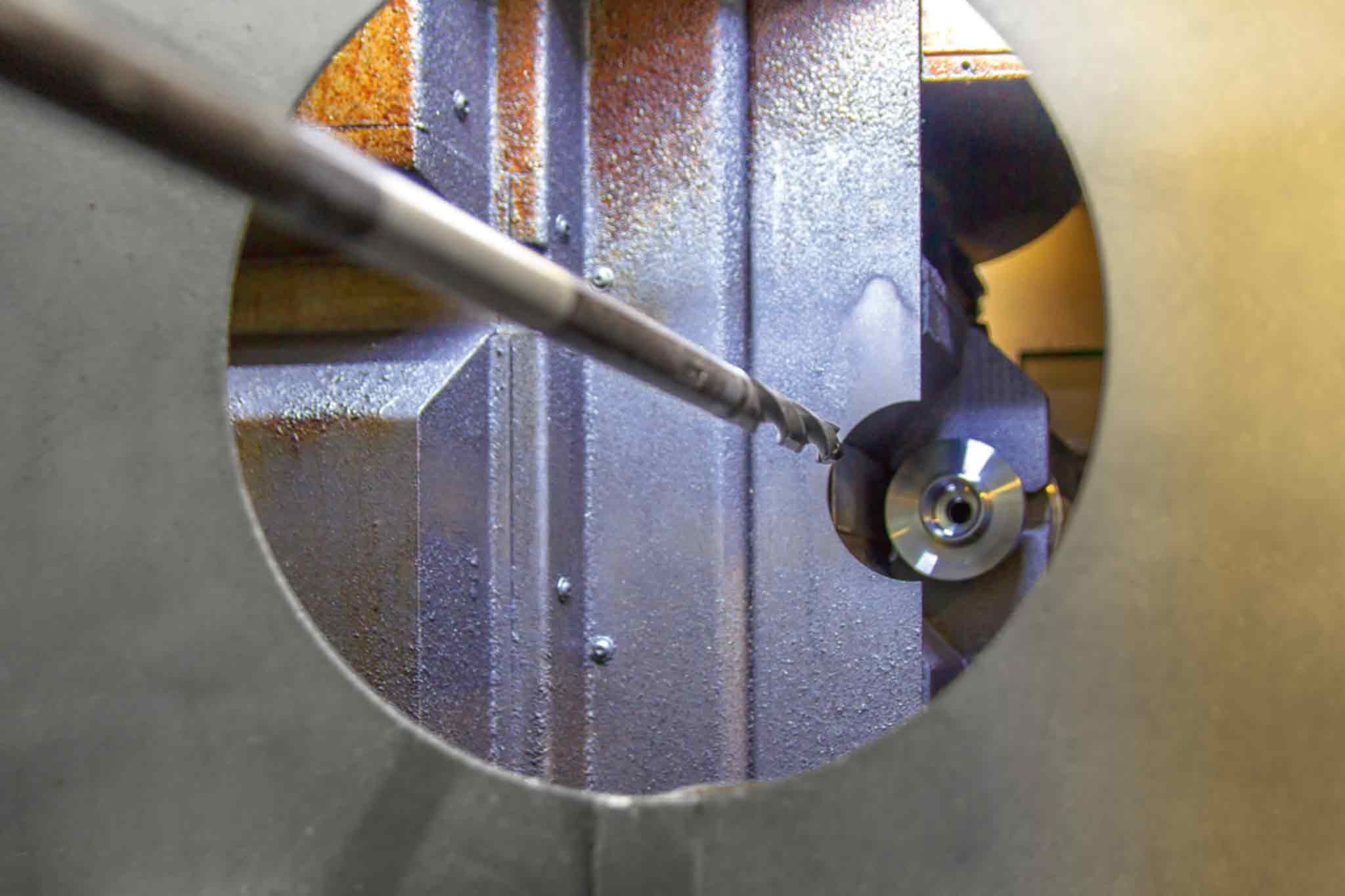
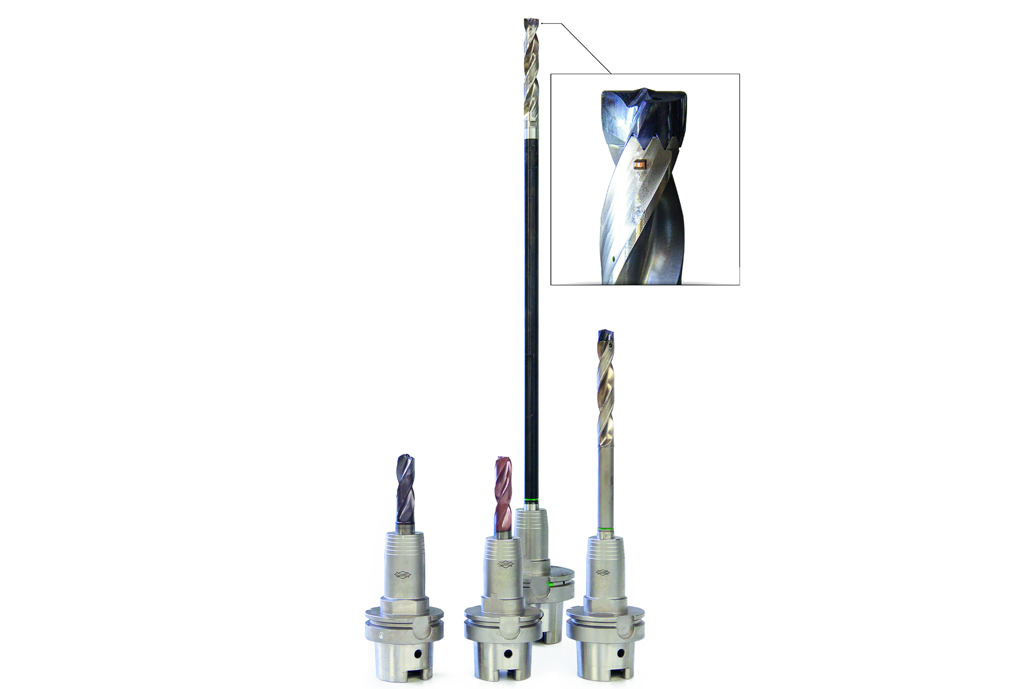
The process for machining the relief bore of the crankshaft made of microalloyed steel is realised with a total of four specially designed tools with two cutting edges. Minimum quantity lubrication is used for cooling. The cover bore is pre-machined with the first solid carbide drill (diameter 19.2 mm). The second solid carbide drill (diameter 18 mm) manufactures the pilot bore through the first bearing. A replaceable head drill (diameter 18 mm) is used as the third machining step. It finishes the first bearing and drills through the second bearing. The remaining bearings are machined with an additional, long replaceable head drill TTD (diameter 18 mm) from MAPAL. This tool threads through the first two bearings at slow speed and low feed, supports itself in it and achieves the best results for machining the remaining bearings despite the long projection length. This specially designed replaceable head drill consists of a holder made of steel with CFS connection, a CFS replaceable head holder with a length of 119.2 mm
and finally the TTD replaceable head made of solid carbide. When machining the crankshaft of a 6-cylinder engine, the holder with CFS connection alone is 480 mm long.
and finally the TTD replaceable head made of solid carbide. When machining the crankshaft of a 6-cylinder engine, the holder with CFS connection alone is 480 mm long.
Burr formation when starting up the series
The four-stage machining process provided the desired results in the trials and series production with a low quantity. However, a problem occurred when starting up series production. A burr formed at the inlet and outlet of the individual bearing bores after around 100 bores that got bigger with each machined bore. The drill heads of the third and fourth drill already had to be changed after 100 bores. This is because the mechanical cleanliness of the
component could not be ensured due to the burr. No metal particles may be found on the component. These could be released when operating the unit. Because of this, any residual dirt and every metal particle on the components must be categorically excluded.
component could not be ensured due to the burr. No metal particles may be found on the component. These could be released when operating the unit. Because of this, any residual dirt and every metal particle on the components must be categorically excluded.
A deburring cutting edge is the solution
Those responsible approached MAPAL with this problem. The burr formation should be rectified as quickly as possible. However without using an additional tool for deburring. Otherwise the cycle time would increase and the process would have to be redesigned. MAPAL met this challenge. “We intensively developed solutions in our development department and fitted
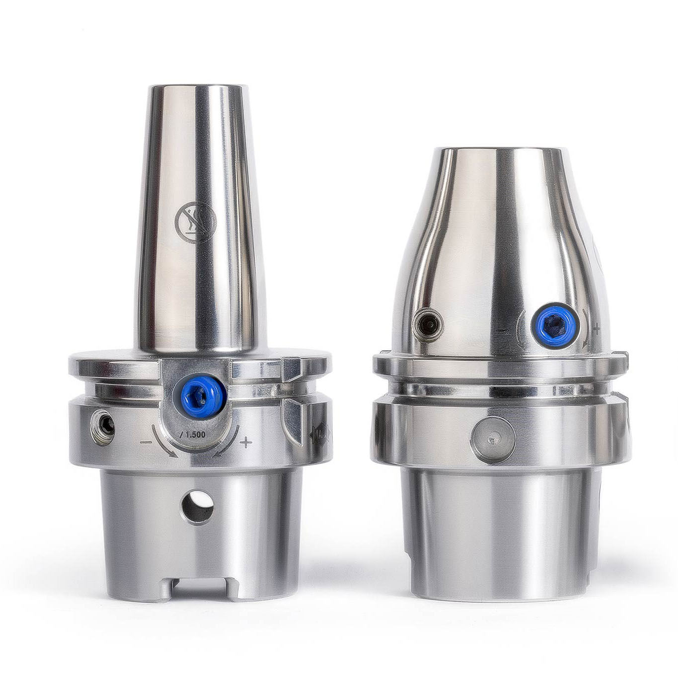
the replaceable head drill that machines all bearings with a deburring cutting edge”, explains Tobias Moser who supervises the project as the responsible MAPAL field service specialist. The deburring cutting edge is spring-loaded and attached directly after the connection for the replaceable head at the CFS replaceable head holder. In the forward movement, the bore entrances are deburred and the bore outlets when the drill moves back.
the replaceable head drill that machines all bearings with a deburring cutting edge”, explains Tobias Moser who supervises the project as the responsible MAPAL field service specialist. The deburring cutting edge is spring-loaded and attached directly after the connection for the replaceable head at the CFS replaceable head holder. In the forward movement, the bore entrances are deburred and the bore outlets when the drill moves back.
The long drill enters the bore for drilling with a feed speed of 200 mm/min. At a defined point, the feed speed is reduced to 125 mm/min over a path of 4 mm. On this path, the deburring cutting edge generates the chamfer at the bore entrance and is simultaneously pressed into the interior of the holder by the spring system. The bore can then be machined with a feed speed of
375 mm/min. The retraction takes place in the same way.
375 mm/min. The retraction takes place in the same way.
Mass production since September 2017
At the start of 2017, MAPAL tested the new concept in the research and development department with an original crankshaft. “With these results, we could work well and further optimise the tool”; says Moser. The result and speed of the optimisation was impressive.
Things got serious in summer. The modified tool with deburring cutting edge was tested on the machine for series production. The result was also desirable here, and the process including forward and backward deburring of the bores has been used since September 2017 in large-scale production. “Thanks to the deburring cutting edge, the service life of the tools is also much longer than before”, says Tobias Moser. The first two drills are replaced after 2,000
bores and the drill heads of both replaceable head drills after 800 bores. And the deburring cutting edge? It only has to be replaced after 25,000 bores. This means that this process is the new standard for the relief bore of the crankshaft. And it has now been transferred to two other lines.
bores and the drill heads of both replaceable head drills after 800 bores. And the deburring cutting edge? It only has to be replaced after 25,000 bores. This means that this process is the new standard for the relief bore of the crankshaft. And it has now been transferred to two other lines.

Reduce cycle time with the Tritan-Drill
Despite the reliable and satisfactory process, work on improvements and optimisation of the tools is naturally being continued. The first step was to reliably manufacture in large-scale production. Now the task is to make machining even more economical. A first step in this direction has already been taken. “We first used the deburring cutting edge uncoated. Now it
is provided with a special PVD coating for an even longer service life”, explains Tobias Moser. To be able to obtain higher machining values and therefore further reduce the cycle time, the same process is also currently tested on a test machine with counterparts with three cutting edges, different designs of the Tritan-Drill. And the results were very promising, reveals Moser: “If everything goes as expected, we will be able to implement the tools this year.”
is provided with a special PVD coating for an even longer service life”, explains Tobias Moser. To be able to obtain higher machining values and therefore further reduce the cycle time, the same process is also currently tested on a test machine with counterparts with three cutting edges, different designs of the Tritan-Drill. And the results were very promising, reveals Moser: “If everything goes as expected, we will be able to implement the tools this year.”