03.11.2022
Efficient deburring with robots
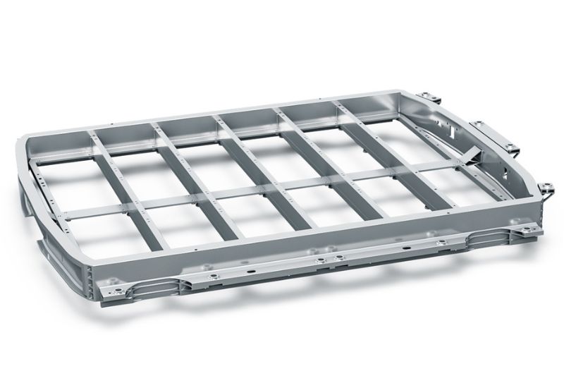
KADIA system processes battery trays
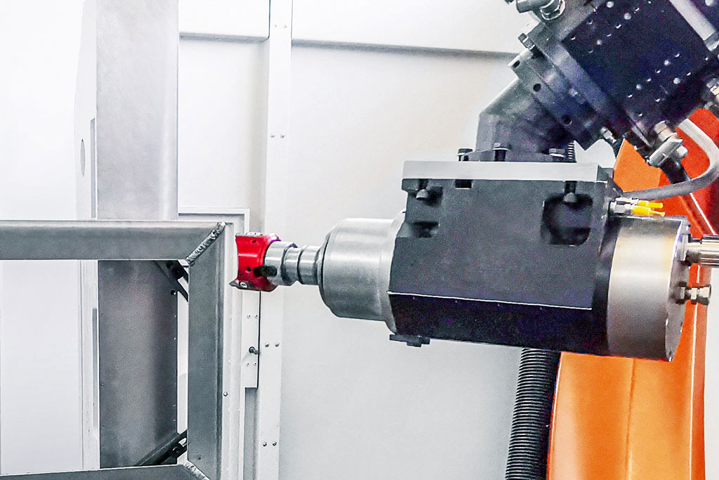
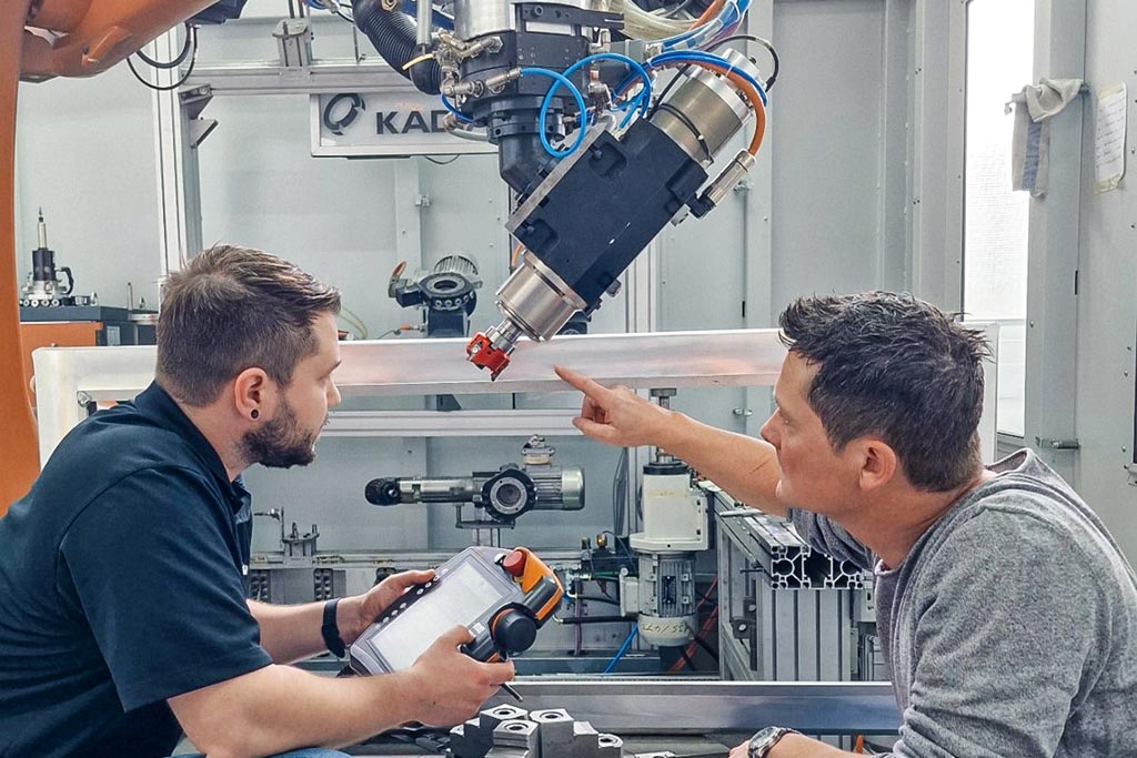
If a milling cutter is guided by a robot, the machining is fundamentally more unstable than on a machining centre. To reliably ensure the shortest cycle times in industrial production in this instance, KADIA is using MAPAL’s FlyCutter with three cutting edges in a newly developed system with three robots for deburring battery trays for electric vehicles.
ニュルティンゲンに本社を置くKADIA Produktion GmbH + Co.社の歴史は、1959年のホーニング工具の製造から始まりました。最初のホーニング盤は創業から10年後に開発されました。1981年同社はバリ取り機の製造と共に、別の事業分野に参入しました。現在、KADIA社はホーニングおよびバリ取り技術のリーディング・スペシャリストであり、200名の従業員を擁しています。
主な顧客は、自動車メーカーやサプライヤー、建設・農業機械メーカー、風力発電所メーカー、航空宇宙産業などです。同社は、ホーニング加工用にさまざまなサイズの標準機を提供してますが、バリ取り加工用には原則としてカスタムマシンを製造しています。顧客にはバリ取りのエキスパートとしてKADIA社を採用する大手機械メーカーも含まれています。
バリの鉛筆テスト
Bei der mechanischen Bearbeitung unterscheidet man zwischen losen und festen Graten. Nach dem Entgraten soll das Bauteil je nach Anforderung scharfkantig, mit Kantenverrundung oder mit einer Fase ausgestattet sein, weshalb hier auch von Kantendesign gesprochen wird. Zur Beurteilung eines losen Grats setzt KADIA einen ebenso simplen wie aussagkräftigen Test ein, für den die um fünf Millimeter ausgefahrene Mine eines Druckbleistifts dient. Kann der Grat damit entfernt werden, ist er lose. Bricht die Mine ab, hat man es mit einem festen Grat zu tun, der je nach Anforderung weggefräst werden muss oder stehen bleiben darf, da er sich später nicht löst.
Für die Bearbeitung mit einem Roboter ist auch die Größe des Werkstücks entscheidend. Bei kleineren Bauteilen wird die Führung des Werkstücks favorisiert. Der Roboter fährt dabei das Werkstück an fest montierten Bearbeitungseinheiten entlang. Bei einer Werkzeug-geführten Strategie bearbeitet der Roboterarm ein fest eingespanntes Werkstück. „Bei großen Werkstücken bin ich mit dem Fräser in der Hand wesentlich geschickter, als wenn ich das sperrige Teil bewegen muss“, erläutert Jannik Weiss, Vertrieb Entgratmaschinen bei KADIA.
Zerspanung in der Versuchszelle
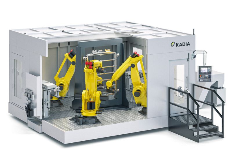
Kernstück der Entwicklung bei KADIA ist eine fünf mal sechs Meter große Versuchszelle mit einem Sechs-Achs-Industrieroboter und einer Schnellwechseleinheit. Hier kann der Prozess der späteren Anlage bereits getestet werden. Vorversuche ermitteln die optimalen Schnittdaten und prüfen die Stabilität. In der Zelle befinden sich 15 einwechselbare Einheiten, auf neun davon hat der Roboter einen automatisierten Zugriff mit einem Aktionsradius von 2,70 m. Eine Einheit stellt eine bestimmte Funktion dar, die für die Bearbeitung eines Bauteils gebraucht wird. Typischerweise besteht sie aus einer Motorspindel mit Schnittstelle und einem Zerspanungswerkzeug.
Ein Rundtisch als siebte Achse gehört ebenfalls zur Ausstattung der Versuchszelle, die zudem über genügend Freiraum verfügt, um weitere Anlagen, wie etwa eine Kühlmittelversorgung oder zusätzliche Prozesseinheiten unterbringen zu können. Oft sind bei KADIA gleich mehrere Teile für verschiedene Versuche in der Zelle gerüstet.
For initial preliminary tests on a dummy part for the battery tray, KADIA used a round-insert milling cutter already in stock in. The tool proved wholly unsuitable for the task. The vibrations that occurred were so severe that even the processing spindle was damaged. Even with low cutting values, the background noise during milling was still noticeable in the adjacent building.
With the task to deliver a suitable milling cutter for the aluminium housing, MAPAL was chosen as the partner of choice. “We evaluate in advance in which tool manufacturer we see the potential for cooperation,” says Jannik Weiss. Although KADIA initially focuses on standard tools, it was a major plus for MAPAL that the tool manufacturer produces custom tools where necessary.
Two milling cutters to choose from
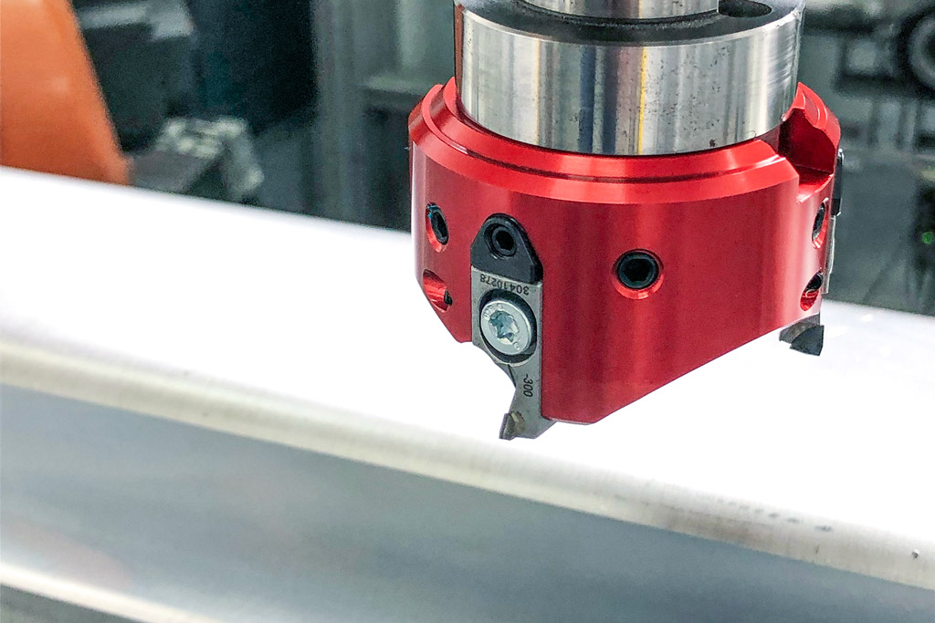
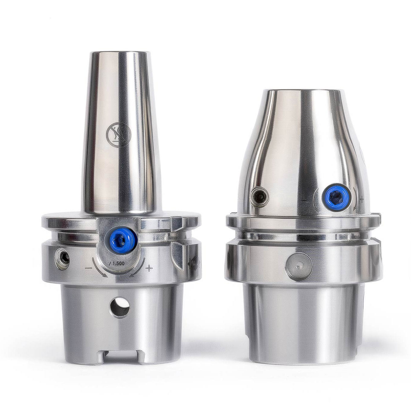
But Norbert Meier, who wanted to show the customer an alternative with the second milling cutter, had reckoned with this outcome. “We specially developed our FlyCutter for requirements like these,” he explains. MAPAL developed the lightweight tool specifically for unstable machining requirements that occur in robot applications. It is optimised for small connections such as BT30. The innovative design and use of aluminium ensure the milling head is particularly lightweight. With the diameter of 63 millimetres used at KADIA, the PCD milling head, including milling inserts, weighs just 220 grams.
The sensitive wedge adjustment make µ-precise adjustment of the milling inserts possible. The dovetail guide and an additional worm screw ensure perfect seating and high accuracy of repetition for the assembly of the milling inserts. The special, ultra-positive cutting edge geometry means only weak forces are applied to the part and the tool spindle guided by the robot.
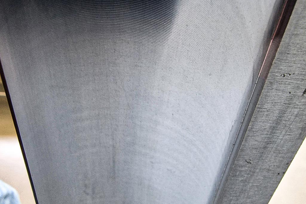
When machining the battery tray, accuracy down to the µm is not required. In fact, to ensure the sealant applied by the automotive manufacturer holds better, a certain rawness of the surface is needed. Only the waviness must not be too high. In the tests, the milling cutter was moved beyond the limit to determine up to which point chatter marks on the relatively thin part still lay within the required tolerance.
切削データと位置決めが鍵
「ロボット加工の核心は、工具、治具、ロボットの相互作用です」とノルベルト・マイヤー氏は説明します。剛性は加工における基本的な問題です。ロボットアームが伸びれば伸びるほど、加工は不安定になります。そのためKADIAは様々な切削データをテストするだけでなく、ワークの前や横などのロボットの様々な位置もテストします。
このケースでは、主軸回転数11,000 rpmでの最適な切削データは、送り0.16 m/s、材料除去率0.5 mmであるとパートナーは判断しました。Fly Cutterは非常に優れた表面品質を確実に実現しました。KADIA社はこのテストデータをカスタムマシンのコンセプトに組み込みました。このためメーカーは、1つのセルに3台のロボットを使用することが、連続生産において最もコスト効率の良いソリューションになると判断しました。2台が前面加工を分担し、3台目が背面加工を行います。切削データに加え、KADIA社 は加工ステップの所要時間と達成可能なサイクルタイムを顧客に提供します。従って大型バッテリートレイのバリ取りには約80秒かかります。「ロボット加工では、このような切削データのプロセス情報はCNCマシンのように標準的なものではありません。ロボットの位置によって、同じデータでも異なる結果が得られます。」とヤニック・ヴァイス氏は話します。
KADIAとMAPALは、この好結果を受け、さらに協力関係を深めたいと考えています。様々な加工プロセスに対する更なるテストが既に計画されています。

Contact
Kathrin Rehor Public Relations Kathrin.Rehor@mapal.com Phone: +49 7361 585 3342