Cylinder crankcase
The cylinder crankcase, also known as the engine block, is the central element of the combustion engine. Depending on the vehicle model and engine size, different models and sizes are available, from the 2-cylinder series engine to the 12-cylinder engine in V-configuration. In the automotive sector, aluminium alloys are mainly used due to the weight advantage. For the cylinder bore, this requires the use of cast sleeves or wear-resistant Coatings to ensure a high mileage. In machining, this often involves mixed machining with aluminium and cast iron and the use of extremely abrasive coatings. The higher combustion pressures in modern engines increase mechanical and thermal loads, resulting in more stringent quality requirements for the features to be machined.

Key features


1. Cylinder bore
PROCESS CONDITIONS
- Schwankende Guss- und Aufmaßsituationen
- Teilweise werden verschleißfeste Beschichtungen (LDS-Schicht) in die Bauteile integriert
- Teilweise Mischbearbeitungen durch den Einsatz verschiedener Werkstoffe
-> Aluminium Kurbelgehäuse und Grauguss Zylinderlaufbuchse - Schwer zugängliche Bearbeitungen aufgrund der Bauteilgröße
- Durchmessertoleranz vor dem Honen bis zu 40 μm

Grundbohrung
1. Vorbearbeitung
Aufbohrwerkzeug
- Stabile und wirtschaftliche Werkzeugauslegung mit Wendeschneidplatten und einfach einstellbaren Kurzklemmhaltern auch für schwankendes Bauteilaufmaß.
2. Fertigbearbeitung
Feinbohrwerkzeug mit EA-System
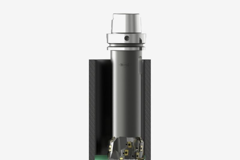
- Mehrschneidiges, kompaktes Werkzeugdesign für höchste Vorschubgeschwindigkeiten und einfaches Einstellen.

Zylinderlauffläche mit Buchse
3. Fertigbearbeitung
Kompensationswerkzeug (Bearbeitungszentrum)
- Schneidenkompensation über stirnseitige Verzahnung automatisch und direkt in der Maschine umsetzbar. Schneidenabhebung durch Positionsversatz und spezielles Werkzeugdesign ermöglichen kontaktfreien Rückzug.
ODER
Aussteuerwerkzeug (Sondermaschine)
- Je nach Maschinentyp werden über eine Zugstange, eine Verstellspindel oder einen Drehantrieb die Schneiden definiert ein- und ausgesteuert. Dies ermöglicht einen kontaktfreien Rückzug sowie eine exakte Nachjustierung der Schneide.

Zylinderlauffläche
4. Honfreigang
Zirkularfräser (Bearbeitungszentrum)
- Mehrschneidige Werkzeugauslegung mit höchster Flexibilität bei der Auswahl der Wendeschneidplatten.
ODER
Aussteuerwerkzeug (Sondermaschine)
- Definiertes Aussteuern der Schneiden durch Zug-/Druckstange. Flexibler Konturzug möglich.
2. Water pump bore
- Multi-stage bore with defined radius transitions
- Diameter tolerances in H8 range
- Circularities of 10 – 20 μm

1. Semi-finishing
PCD step boring tool
PCD step boring tool
- Optimised PCD insert geometry for controlled chip breaking and with interchangeable solid carbide drill for efficient use of cutting edges on boring stages.
3. Crankshaft bearing bore
PROCESS CONDITIONS
- High coaxiality of the individual bearing journals to each other
- Repeated cutting due to the interrupted cut
- Mixed machining for fine machining through bearing shells
- Diameter tolerances of 0.2 mm
- Surface specifications of Rz 3.2 μm
- Circularity < 3 μm

Maximum productivity with one-shot solution
1. Pre- and finishing machining
Precision line boring bar
- Optimum coaxiality on the component due to additional bearings opposite the machine spindle, including for long component lengths.

Ultimate process reliability with 2-step process
Pre- and Finishing
Fine boring tool
Fine boring tool
- Pre-machining stage and additional micro-machining at the finishing stage for the highest quality requirements and process reliability.