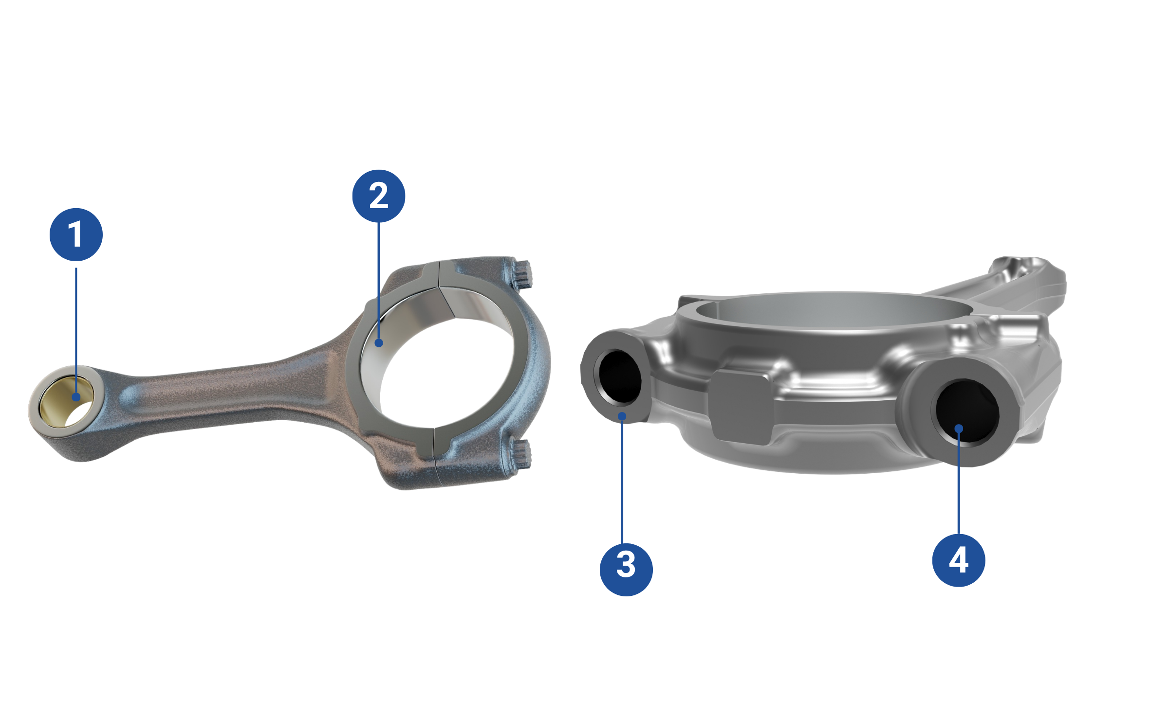
Connecting rod
Connecting rods are subject to high dynamic loads in engine operation. High-strength steel materials like 70MnVS4 or C70 are used to meet these requirements. Their role: To convert the linear motion of the piston into a rotating motion of the crankshaft. To minimise the moving mass, connecting rods are consistently optimised for weight. The result is a wide range of variants – from parallel and trapezoidal to step shapes. This variety poses stringent requirements for manufacturing, particularly in machining the small end of the connecting rod. Different geometries result in varying spot drilling situations that must be resolved with precision and cost-effectiveness. Cost-effectiveness is a priority in series production. The high quantities require stable processes, short cycle times and maximum tool lives.
/19-1-1-.jpg)
/19-2-1-.jpg)
/19-3-1-.jpg)
1. Small end
PROCESS CONDITIONS
- Spot drilling and boring due to different connecting rod shapes
- Surface requirements of maximum Ra 0.8 μm
- Diameter tolerances of 6 μm
- Circularities of 5 – 10 μm
- Partly specified bore shapes such as the bell-mouthed shape

The right solution for every requirement
1. Pre-machining
WP solid drill
WP solid drill
- Short, sturdy tool design enables drilling from solid, boring and chamfering on both sides with just one tool.

2. Semi-finishing and finishing machining
Fine boring tool
- Pre-machining stage for maximum tool life and for the stringent quality requirements of the fine boring stage.
or
HPR replaceable head reamer
- Multi-blade, regrindable replaceable head for short processing times and long tool lives.

The right solution for every contour
3. Finishing
Fine boring tool
- Pre-machining stage and adjustable WP fine machining stage for the most stringent quality requirements and maximum tool life.
or
Actuating tool
- Additional U axis for semi-finishing and finishing machining for big and small end. Maximum contour flexibility and simple wear contour.
2. Big end
PROCESS CONDITIONS
- Verschleißfestes Hartmetall an der Crackkerbe
- Unterschiedliche Aufmaßsituationen
- Höchste Qualitätsanforderungen an die Bohrungsgeometrie
- Rundheiten von 5 - 8 μm
- Durchmessertoleranzen von 10 μm
- Definierte Oberflächenwerte von ~ Rz 6 μm bis Rz 11 μm.

1. Vorbearbeitung
Schruppenwerkzeug
- Stabiles, mehrschneidiges Werkzeugdesign für die Kombination mehrerer Prozessschritte (Schruppen, Aufbohren, Fasen).
2. Fertigbearbeitung
Feinbohrwerkzeug
- Auf- und Feinbohren für definiertes Aufmaß, maximale Standmenge und höchste Qualitätsanforderungen.
3. Bolt locating surface / Bolt hole bore
PROCESS CONDITIONS
- Positional accuracy of +/- 0.10 mm
- Surface finish requirement Ra 3.2 μm
- Concentricity 0.20 mm
- Diameter tolerances 0.05 mm to 0.10 mm
- Bore design with multiple step changes
- Materials difficult to machine with additional hard-forged outer skin