Turbolader
Um Leistung und Effizienz moderner Verbrennungsmotoren zu steigern, kommen Abgasturbolader zum Einsatz. Die komprimierte Luftzufuhr erhöht den Wirkungsgrad und senkt gleichzeitig den Emissionsausstoß – ein zentraler Aspekt aktueller Klimastrategien. Bei Drehzahlen von bis zu 300.000 min-1 gelten höchste Anforderungen an Koaxialität und Rundheit. Besonders auf der Abgasseite (Heissseite) stellen hochlegierte, abrasive Werkstoffe extreme Anforderungen an die Verschleißfestigkeit der Zerspanungswerkzeuge. Schon geringe Verbesserungen der Standmenge pro Werkzeug führen bei hohen Stückzahlen zu signifikanten Kostenvorteilen in der Serienfertigung.

1. Turboladergehäuse
Prozessbedingungen
- Highly heat-resistant and ultra-abrasive materials
- Complex geometries and contours with chamfers, radii and transitions
- Tight form, position and surface tolerances
- Interrupted cuts

Heissseite
1. Internal contour machining
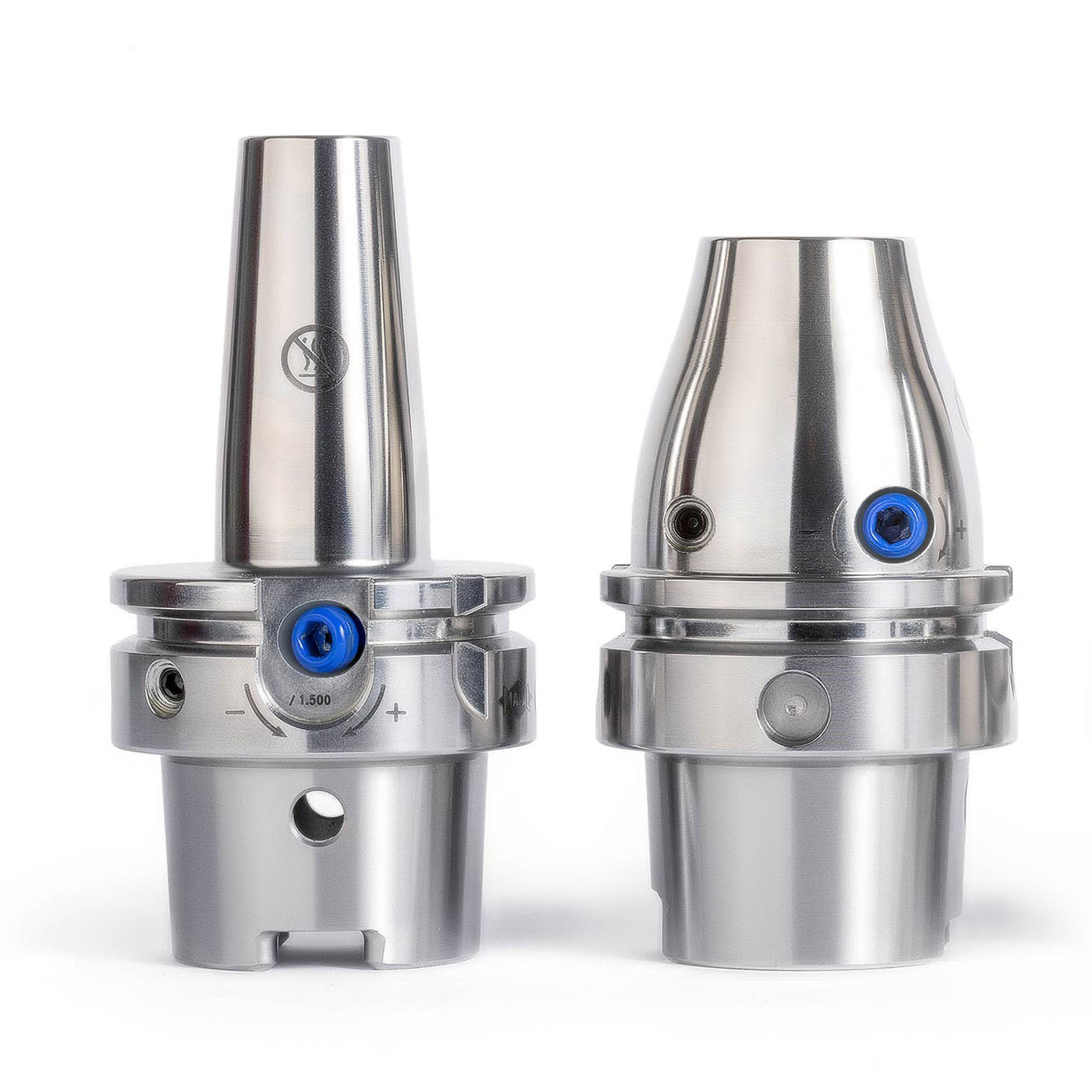
TOOLTRONIC® tool
- Flexible machining with an additional machining axis (U axis) with maximum flexibility for contour changes or wear corrections.

2. Anschlussbearbeitung Abgaskrümmer
Aufbohrwerkzeug
- Werkzeugdesign mit einstellbaren Wendeschneidplatten für kurze Prozesszeiten.

Shoulder milling of surfaces
NeoMill-4-Corner
NeoMill-4-Corner
- Short, sturdy tool design for maximum stability and specially developed indexable inserts for workpiece materials that are difficult to machine.
2. Impeller / vane wheel

Key features
HOT SIDE:
1. Shaft bore
2. Balancing surface
COLD SIDE:
1.Shaft bore
2. Balancing surface
3. Vane machining
PROCESS CONDITIONS
- Workpiece materials that are difficult to machine on the hot side
- Material fluctuations and alloy differences
- Complex machining in hard-to-reach places
- High-precision requirements for radial run-out
- Surface requirements of Ra < 0.4 μm

Hot Side
1. Shaft bore
MEGA-Speed-Drill-Titan
- Special cutting geometry and coating that reduces the formation of built-up edges and optimises chip removal.
2. Balancing Surface
Profile milling cutter
- Multi-blade, coated solid carbide milling cutter, developed for workpiece materials that are difficult to machine.

Cold Side
1. Shaft bore
Tritan-Drill-Alu
- Three-blade solid carbide drill for the highest feeds.
2. Balancing Surface
PCD shoulder milling cutter
- Multi-blade PCD-tipped milling cutter for the longest tool lives.
3. Vane machining
Coated form cutters
- Form cutters adapted to the component contour for roughing, semi-finishing and finishing.