Turbocharger
Exhaust gas turbochargers are used to boost the performance and efficiency of modern combustion engines. The compressed air supply increases efficiency while reducing emissions – a key aspect of current climate strategies. The most stringent requirements for coaxiality and circularity apply at speeds of up to 300,000 rpm. Particularly on the exhaust side (hot side), high-alloyed, abrasive workpiece materials pose extreme requirements for machining tool wear resistance. At high quantities, even small improvements in tool life for each tool lead to significant cost advantages in series production.

1. Turbocharger housing
- Highly heat-resistant and ultra-abrasive materials
- Complex geometries and contours with chamfers, radii and transitions
- Tight form, position and surface tolerances
- Interrupted cuts

Hot Side
1. Internal contour machining
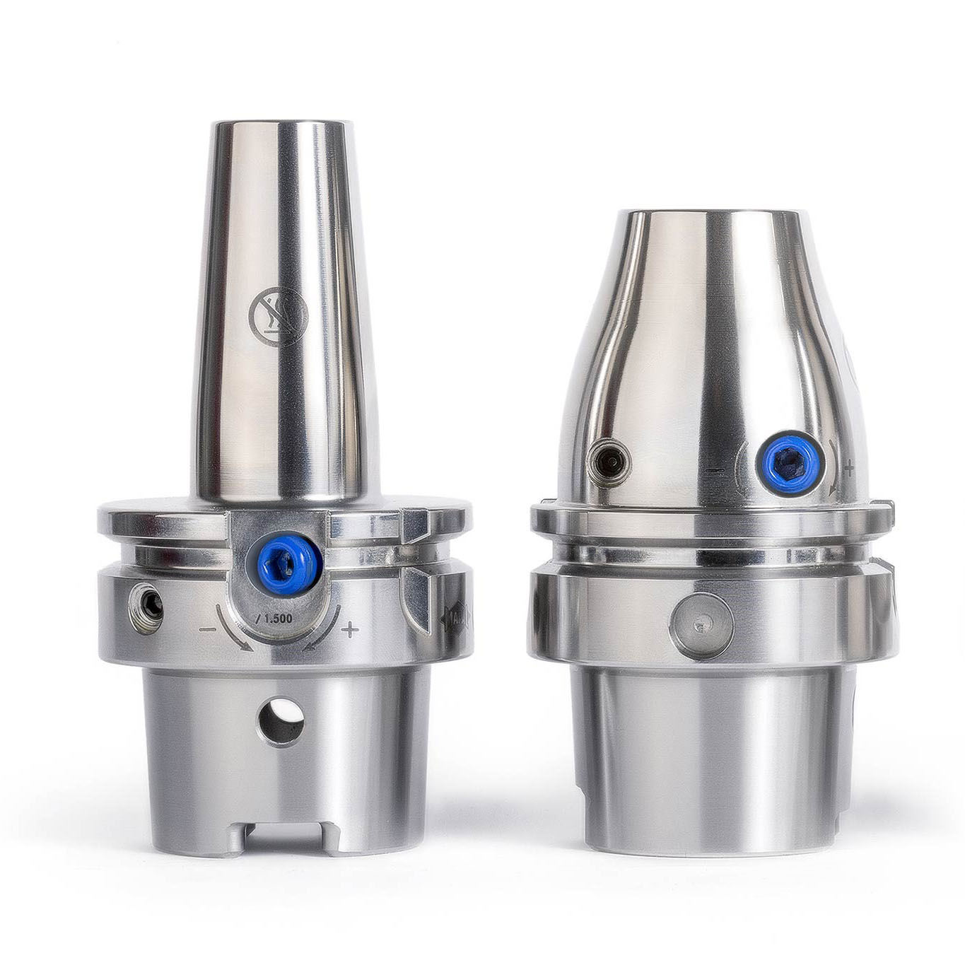
TOOLTRONIC® tool
- Flexible machining with an additional machining axis (U axis) with maximum flexibility for contour changes or wear corrections.

Boring tool
- Tool design with adjustable indexable inserts for short processing times.

High-performance reamer
- Tool design with specially arranged inserts for optimal chip removal, including at the highest feeds

NeoMill-16-Face
- Maximum number of teeth and indexable inserts with 16 cutting edges for maximum tool lives and low costs per component.

NeoMill-4-Corner
- Short, sturdy tool design for maximum stability and specially developed indexable inserts for workpiece materials that are difficult to machine.
2. Impeller / vane wheel

Key features
HOT SIDE:
1. Shaft bore
2. Balancing surface
COLD SIDE:
1.Shaft bore
2. Balancing surface
3. Vane machining
- Workpiece materials that are difficult to machine on the hot side
- Material fluctuations and alloy differences
- Complex machining in hard-to-reach places
- High-precision requirements for radial run-out
- Surface requirements of Ra < 0.4 μm

Hot Side
1. Shaft bore
MEGA-Speed-Drill-Titan
- Special cutting geometry and coating that reduces the formation of built-up edges and optimises chip removal.
2. Balancing Surface
Profile milling cutter
- Multi-blade, coated solid carbide milling cutter, developed for workpiece materials that are difficult to machine.

Cold Side
1. Shaft bore
Tritan-Drill-Alu
- Three-blade solid carbide drill for the highest feeds.
2. Balancing Surface
PCD shoulder milling cutter
- Multi-blade PCD-tipped milling cutter for the longest tool lives.
3. Vane machining
Coated form cutters
- Form cutters adapted to the component contour for roughing, semi-finishing and finishing.